
LCD I2C Adapter Board
₹215.00Current price is: ₹215.00. Original price was: ₹375.00.
5 in stock
Add to cart
Buy Now

You may also like…
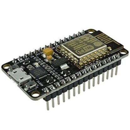
ESP8266 NodeMCU WiFi Development Board (CP2102)
₹370.00Current price is: ₹370.00. Original price was: ₹699.00.Sale!Hot
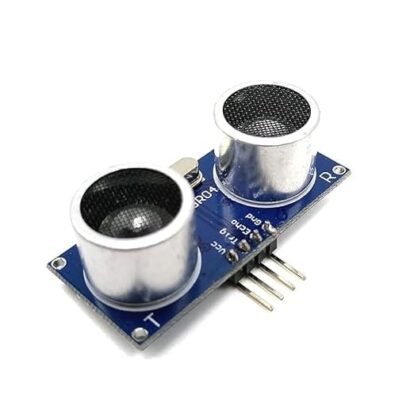
HC-SR04 Ultrasonic Sensor Module
₹236.00Current price is: ₹236.00. Original price was: ₹660.00.Sale!Hot
2 Channel 5V Relay Module Board with Optocoupler Isolation
₹189.00Current price is: ₹189.00. Original price was: ₹276.00.Sale!HotLCD I2C Adapter Board – High-Quality Serial Interface Module for 16×2 and 20×4 LCDs
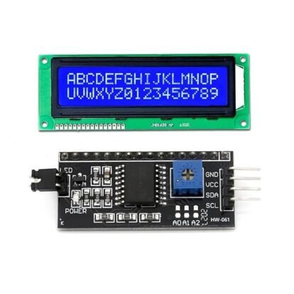
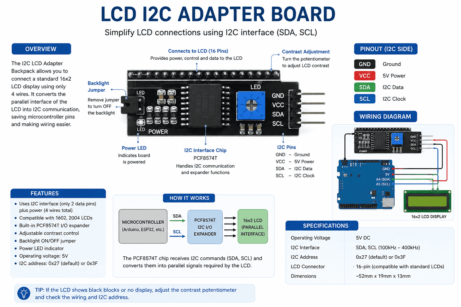
The LCD I2C Adapter Board is a compact serial interface module that simplifies connecting 16×2 and 20×4 character LCD displays to your microcontroller. By utilizing the I2C communication protocol, this module reduces the required data pins from 16 down to just 2 (SDA and SCL). Ideal for Arduino, ESP8266, NodeMCU, and Raspberry Pi projects, it features an onboard potentiometer for contrast adjustment and configurable I2C address jumpers for multi-device setups.
Streamline Your Projects with the LCD I2C Adapter Board
When building DIY electronics, robotics, or IoT prototypes, microcontrollers like the Arduino Uno or NodeMCU quickly run out of available digital I/O pins. A standard 16×2 or 20×4 character LCD screen typically requires up to 6 to 10 GPIO pins to operate in 4-bit parallel mode. This heavy pin consumption limits your ability to connect additional sensors, relays, or motor drivers.
The LCD I2C Adapter Board solves this design bottleneck entirely. By acting as an intermediary piggyback board, it translates the standard parallel interface of hitachi HD44780-compatible LCDs into a streamlined, two-wire I2C (Inter-Integrated Circuit) serial interface. With this high-efficiency module, you can regain control over your microcontroller’s pins while keeping your hardware displays clean, organized, and professional.
Key Hardware Features & Performance
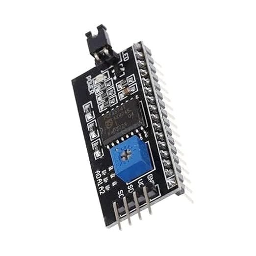
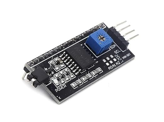
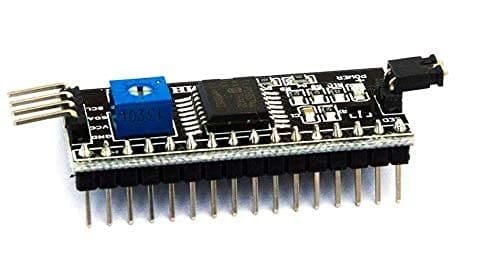
- Reduced Pin Count: Operates using only 4 pins in total: VCC (Power), GND (Ground), SDA (Serial Data), and SCL (Serial Clock).
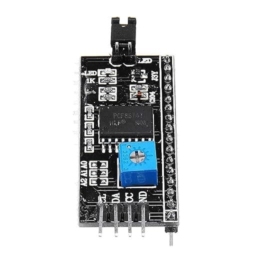
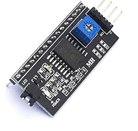
- Integrated Contrast Adjustment: Features a built-in blue trimmer potentiometer. This allows you to fine-tune the screen contrast directly on the back of the board with a small screwdriver, eliminating the need for an external breadboard potentiometer.
- Backlight Control: Includes an onboard jumper cap that permits manual or programmatic control of the LCD backlight. If you need to save power in a battery-operated IoT project, you can easily turn the backlight off through your code.
- Expandable I2C Addressing: Built around the widely supported PCF8574 I/O expander chip, the board includes three address pads (A0, A1, A2). By bridging these solder joints, you can modify the default I2C address (typically
0x27or0x3F), allowing you to cascade up to 8 displays on a single I2C bus.
Universal Microcontroller Compatibility
Whether you are a hobbyist building your first smart home automation hub or an engineer developing an industrial embedded system, this serial interface module offers plug-and-play ease. It operates seamlessly across a wide voltage spectrum ($3.3\text{V}$ to $5\text{V}$ DC), making it directly compatible with:
- Arduino Boards: Uno, Mega, Nano, and Leonardo.
- Wi-Fi Modules: ESP8266, NodeMCU, and ESP32 development boards.
- Single-Board Computers: Raspberry Pi and Orange Pi (using logic level shifters if required).
- STEM Learning Kits: Excellent addition for student electronics labs and prototyping workflows.
How to Connect and Wire Your Module
Wiring the LCD I2C Adapter Board to an Arduino or ESP8266 is incredibly straightforward. Solder the male headers of the adapter directly to the 16 parallel pins on your standard 1602 or 2004 character display. Once secure, connect the 4-pin row to your development board as follows:
- VCC to $5\text{V}$ (or $3.3\text{V}$ depending on your microchip logic)
- GND to Ground
- SDA to the Microcontroller’s I2C Data Pin (e.g., A4 on Arduino Uno)
- SCL to the Microcontroller’s I2C Clock Pin (e.g., A5 on Arduino Uno)
Once wired, simply include the standard LiquidCrystal_I2C library in your programming environment (like Arduino IDE), run an I2C scanner code to confirm your address, and begin printing data to your screen in minutes.
Technical Specifications
| Feature | Details |
| Product Name | LCD I2C Adapter Board |
| Driver Chip | PCF8574T / PCF8574AT |
| Supported Displays | 16×2 (1602) and 20×4 (2004) Character LCDs |
| Operating Voltage | $2.5\text{V}$ to $6.0\text{V}$ DC (Recommended $5\text{V}$) |
| Communication Protocol | I2C / IIC Serial |
| Default I2C Address | 0x27 or 0x3F (Configurable via A0/A1/A2 pads) |
| Dimensions | $41.5\text{mm} \times 19\text{mm} \times 15\text{mm}$ |
| Onboard Controls | Contrast Potentiometer, Backlight Enable Jumper |
Reviews
There are no reviews yet.