- Empty cart.
- Continue Shopping
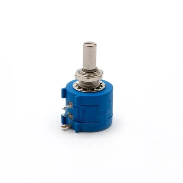
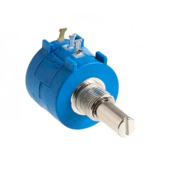
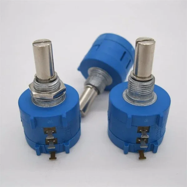
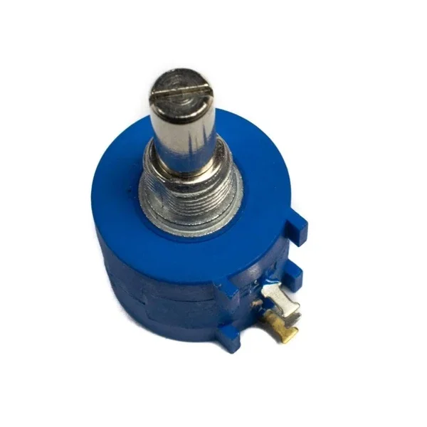
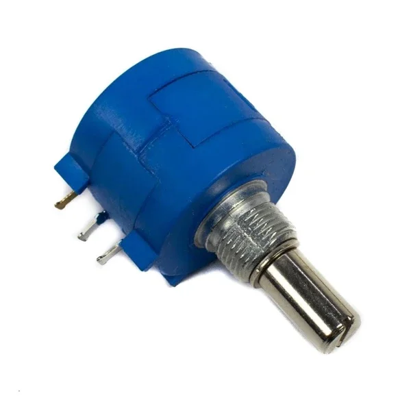
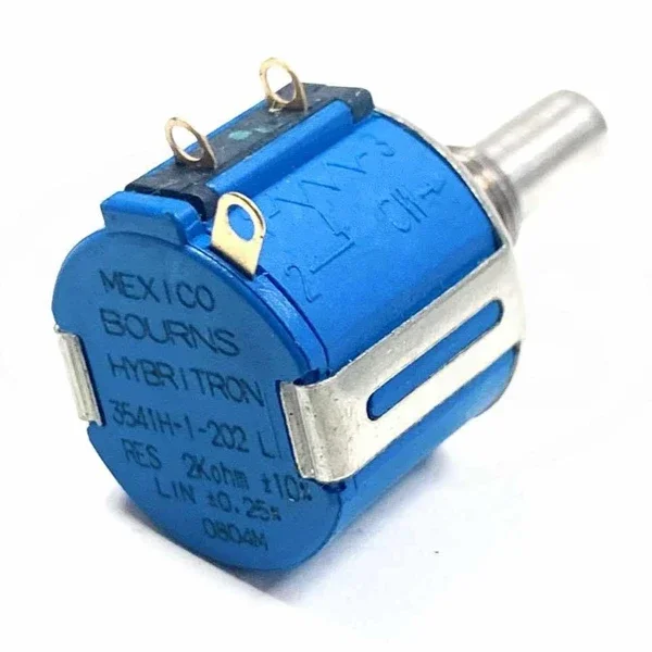

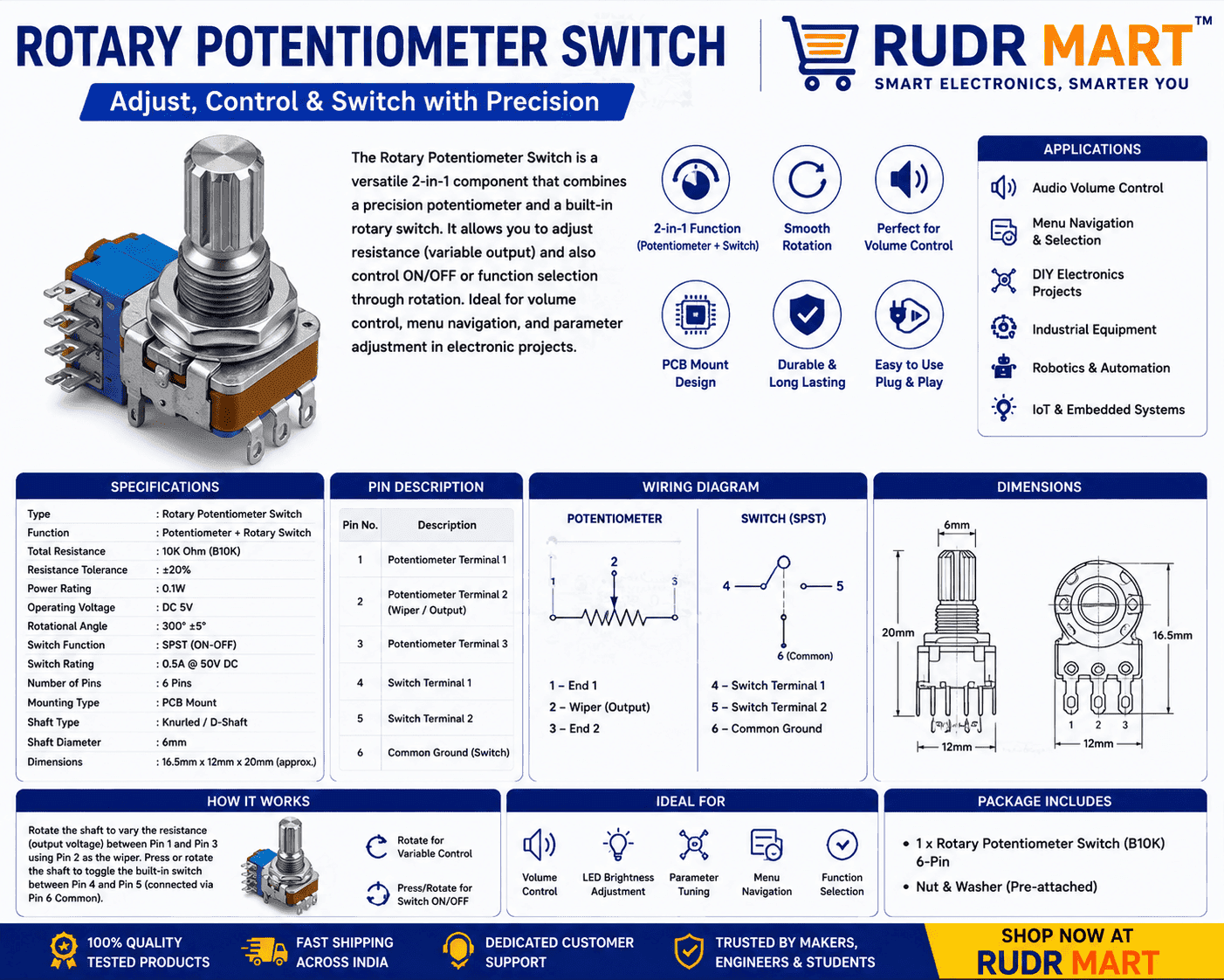
Rotary Potentiometer Switch
₹230.00Current price is: ₹230.00. Original price was: ₹265.00.
Take absolute control over your electronics projects with this premium Rotary Potentiometer Switch. Featuring a highly accurate 20K Ohm linear resistive track, this 3-pin variable resistor offers smooth, continuous adjustments perfect for volume tuning, voltage division, and signal calibration.
Designed for both breadboard prototyping and custom panel mounting, it comes complete with a rugged, ergonomic control knob to protect the metal shaft and add a professional finish to your hardware. Whether you are building an audio amplifier, regulating motor speeds, or tweaking an Arduino project, this versatile component delivers the precision and durability your circuitry demands.
Key Highlights:
Value: 20K Ohm Precision Adjustable Resistor
Hardware: Standard 3-pin layout with included knurled control knob
Taper: Smooth, predictable Type-B Linear Taper
Applications: Ideal for audio equipment, DIY robotics, microcontrollers, and educational electronics kits.
19 in stock (can be backordered)
Add to cart
Buy Now

Rotary Potentiometer Switch: The Ultimate Analog Control Solution
In the world of electronics, precision and reliability are non-negotiable. Whether you are building a custom audio amplifier, tweaking a robotics project, or designing an industrial control panel, the Rotary Potentiometer Switch stands out as an indispensable component. This 20K Ohm precision adjustable resistor with an included knob is engineered to deliver smooth, linear resistance adjustments and dependable performance across countless applications.
As a versatile 3-pin variable resistor, this component allows users to fine-tune electrical signals with absolute accuracy. By combining a high-quality resistive element with a rugged mechanical interface, this Rotary Potentiometer Switch bridges the gap between complex circuitry and intuitive human control.
Key Features of the 3-Pin Variable Resistor
Understanding what goes into your components ensures the success of your hardware designs. This Rotary Potentiometer Switch is packed with features that make it a favorite among hobbyists, makers, and professional engineers alike:
Optimal 20K Ohm Resistance: Perfect for a wide range of voltage division, tuning, and signal conditioning tasks.
Smooth Rotary Action: The internal track is designed for low friction, ensuring a premium tactile feel during adjustments.
Complete Knob Assembly: Comes with an ergonomic, easy-to-grip knob that protects the underlying metal shaft from wear and tear.
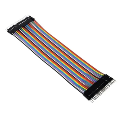
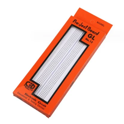
Standard 3-Pin Layout: Fits perfectly into breadboards, prototyping matrices, and custom printed circuit boards (PCBs).
Durable Construction: Built with high-grade materials to withstand thousands of continuous rotations without signal degradation.
Detailed Technical Specifications
When selecting a variable resistor, exact technical parameters are critical to preventing component failure or circuit instability. Below is the detailed breakdown of this Rotary Potentiometer Switch:
| Parameter | Specification |
| Component Type | Rotary Potentiometer Switch / Variable Resistor |
| Resistance Rating | 20K Ohms ($\pm10\%$) |
| Taper Type | Linear (Type B) |
| Terminal Count | 3 Pins (Input, Wiper, Output) |
| Rotation Angle | $300^\circ \pm5^\circ$ |
| Included Accessories | Matching Knurled Control Knob |
| Mounting Style | Panel Mount / Through-Hole PCB |
How the Rotary Potentiometer Switch Works
At its core, a Rotary Potentiometer Switch functions as an adjustable voltage divider. The component contains a resistive track and a wiping contact that moves along it.
$$V_{\text{out}} = V_{\text{in}} \cdot \left( \frac{R_2}{R_1 + R_2} \right)$$
When you connect voltage across the two outer pins, the middle pin (the wiper) samples the voltage at its current position. Turning the knob of the Rotary Potentiometer Switch changes the physical location of the wiper along the track, altering the resistance ratio between the center pin and the outer pins. This mechanical movement results in an immediate, continuous modification of the electrical output.
Common Applications in DIY Electronics
Because of its adaptability, the Rotary Potentiometer Switch finds its way into a massive variety of electronic configurations.
1. Audio and Sound Systems
In audio engineering, controlling volume, gain, and equalization curves requires reliable hardware. This Rotary Potentiometer Switch acts as an excellent volume dial or tone controller in DIY guitar pedals, audio mixers, and custom desktop speakers, providing static-free, continuous sound tuning.
2. Motor Speed Regulation
When paired with a pulse-width modulation (PWM) controller or a micro-controller like an Arduino, the Rotary Potentiometer Switch serves as an intuitive interface for adjusting DC motor speeds or regulating the brightness of high-power LED arrays.
3. Prototyping & Educational Kits
For students and makers working on breadboards, having a reliable Rotary Potentiometer Switch is crucial. It allows you to simulate sensor data, test analog-to-digital converter (ADC) inputs, and calibrate calibration thresholds on the fly without changing fixed resistors.
Installation and Wiring Guide
Wiring a 3-pin variable resistor is straightforward, making the Rotary Potentiometer Switch highly accessible for creators of all skill levels.
Pin 1 (Left): Typically connected to your ground source (GND) or reference low voltage.
Pin 2 (Center Wiper): Connected to your analog input pin (e.g., A0 on an Arduino) or the signal path that requires modification.
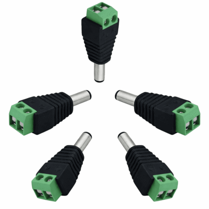
Pin 3 (Right): Connected to your positive voltage supply (e.g., +5V or +3.3V).
Pro Tip: If you notice that your output value decreases when you turn the knob clockwise instead of increasing, simply swap the connections on Pin 1 and Pin 3 to invert the rotary behavior of your Rotary Potentiometer Switch.
Why Choose This Component for Your Next Project?
When sourcing components for your inventory, consistency is key. Inferior variable resistors often suffer from “dead zones” or rotational noise, which can cause erratic jumps in your readings. This premium Rotary Potentiometer Switch guarantees a linear taper that responds predictably to every fraction of a turn. Supported by a robust mechanical chassis and paired with a professional-looking knob, this Rotary Potentiometer Switch delivers long-term durability and aesthetic polish to any project enclosure.
| Weight | 0.25 kg |
|---|---|
| Dimensions | 35 × 2.8 × 28 cm |


Reviews
There are no reviews yet.