- Empty cart.
- Continue Shopping
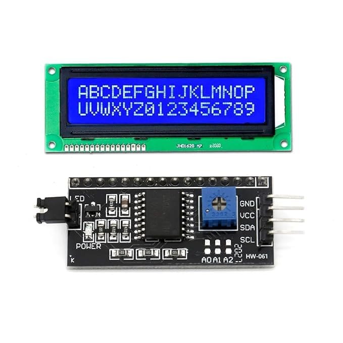
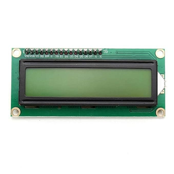
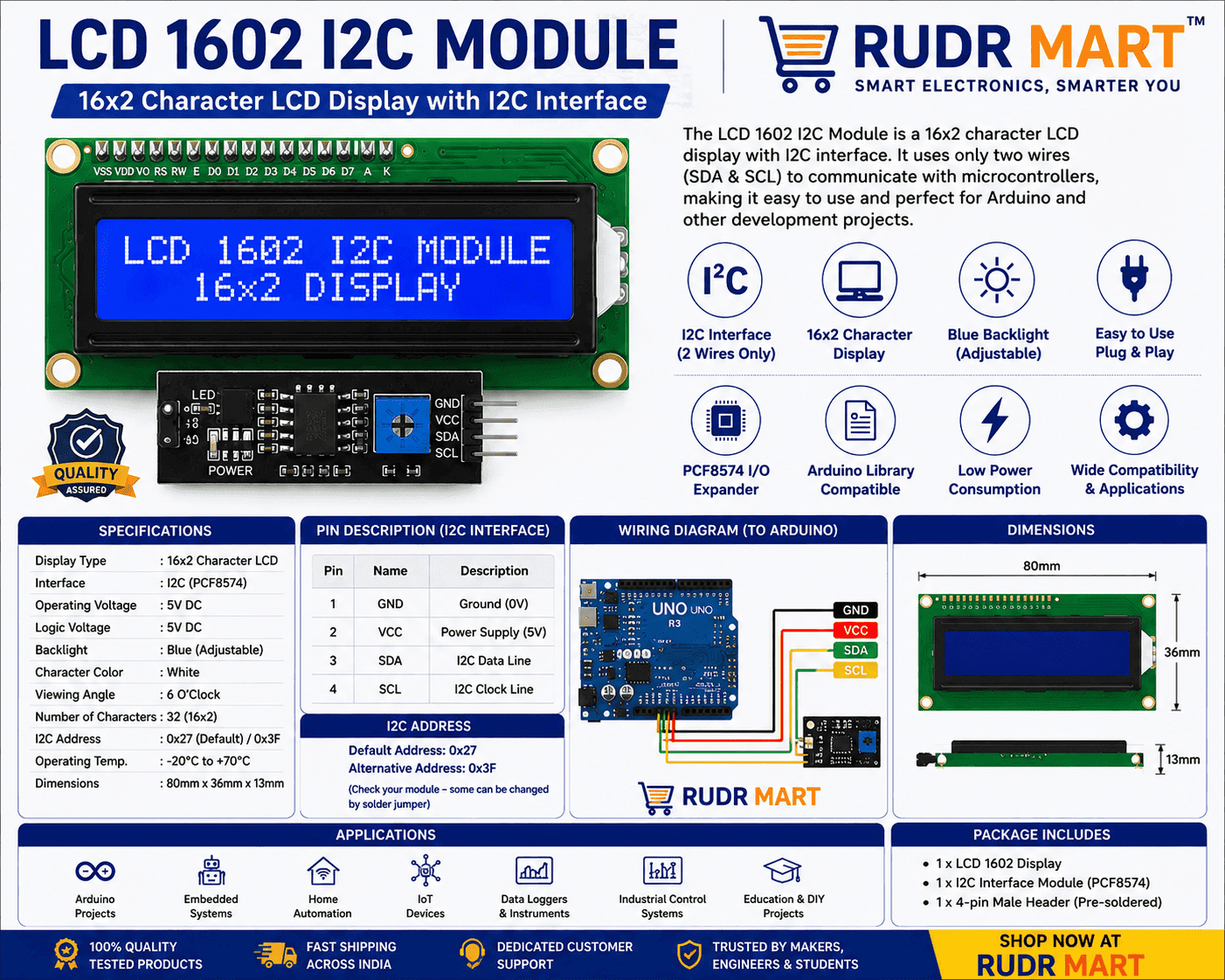
LCD 1602 I2C Module
₹360.00Current price is: ₹360.00. Original price was: ₹860.00.
10 in stock
Add to cart
Buy Now

You may also like…
W5500 Ethernet Network Module
₹325.00Current price is: ₹325.00. Original price was: ₹499.00.Sale!Hot
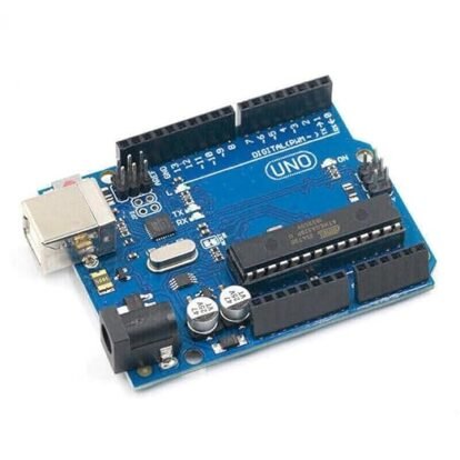
UNO R3 for Arduino ATmega16U2 USB Microcontroller
₹379.00Current price is: ₹379.00. Original price was: ₹579.00.Sale!Hot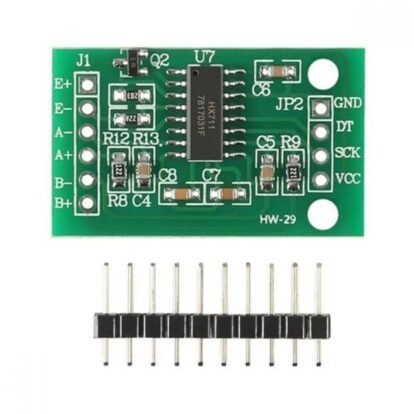
HW-29 Load Cell Amplifier Module
₹197.00Current price is: ₹197.00. Original price was: ₹232.00.Sale!HotIf you want to add a crisp visual output to your project, theLCD 1602 I2C Module is the perfect choice.
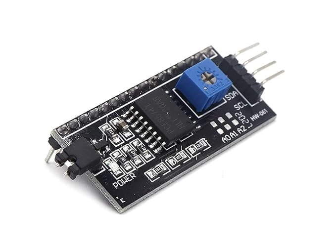
Are you tired of cluttered breadboards and complex wiring schemes ruining your electronics prototypes? The LCD 1602 I2C Module is the ultimate solution for makers, engineers, and hobbyists who need a clean, reliable, and space-saving alphanumeric display. Traditional 1602 parallel LCD screens require up to 16 digital and analog pins on your microcontroller, leaving very little room for sensors, motors, and communication peripherals. By combining a classic 16×2 character display with a pre-soldered I2C (Inter-Integrated Circuit) daughterboard adapter, this module slashes your required data lines down to just two pins (SDA and SCL).
Bring your embedded systems to life instantly. Whether you are constructing an industrial IoT monitoring station, a smart weather tracker, an automated robotics platform, or an educational STEM project, this display offers an efficient, highly readable, and incredibly user-friendly visual interface.
Uncompromising Features and Engineering Performance
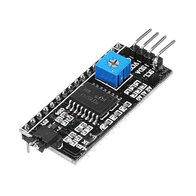
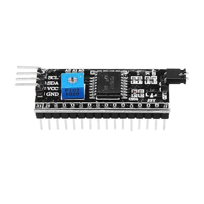
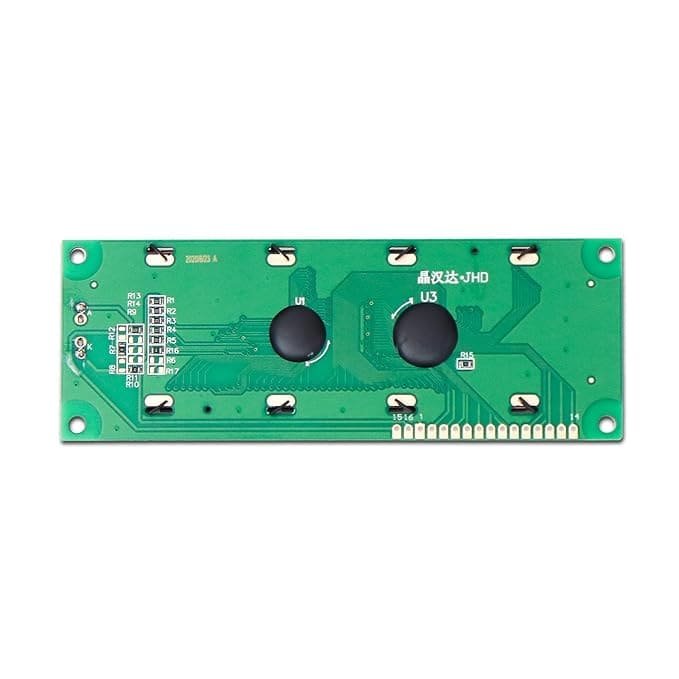
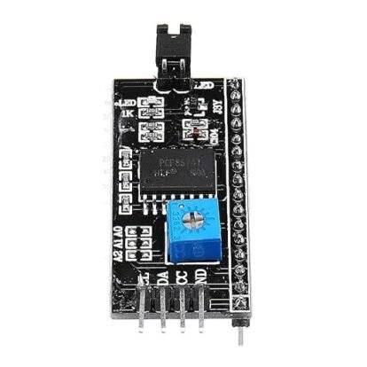
- The LCD 1602 I2C Module features a surface-mounted PCF8574 chip on the back.: Skip the tedious process of manual soldering and massive jumper wire webs. The back of this module features a surface-mounted PCF8574 I2C chip that handles all parallel-to-serial data conversion seamlessly.
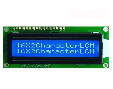
- High-Contrast Vivid Display: Engineered with a bright blue LED backlight and clean white alphanumeric text tracking, this display ensures exceptional readability under indoor ambient lighting.
- Precision Contrast Calibration: Lighting environments change, and so should your display. The integrated onboard physical potentiometer trimmer allows you to calibrate the liquid crystal contrast level with a simple twist of a precision screwdriver.
- Universal Microcontroller Architecture: Designed from the ground up for open-source ecosystems. It operates flawlessly with standard
LiquidCrystal_I2Clibraries, ensuring native plug-and-play operation with Arduino Uno, Mega, Nano, NodeMCU ESP8266, ESP32, and Raspberry Pi boards.
Hardware Reference & Pinout Guide
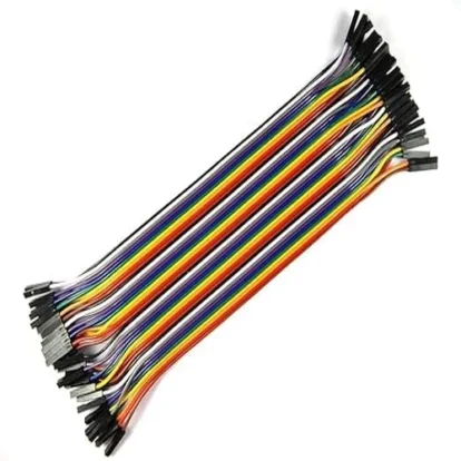
Setting up the hardware is straightforward. Connect the four pins extending from the LCD 1602 I2C Module backpack directly to your development board directly to your development board using standard female-to-female or male-to-female jumper wires:
- VCC: Connect to a stable +5V DC power source.
- GND: Connect to your system’s common ground line.
- SDA (Serial Data Line): Connect to your microcontroller’s dedicated I2C data pin (e.g., Pin A4 on Arduino Uno, Pin 21 on ESP32).
- SCL (Serial Clock Line): Connect to your microcontroller’s dedicated I2C clock pin (e.g., Pin A5 on Arduino Uno, Pin 22 on ESP32).
Pro-Tip on Addressing: The module typically defaults to an I2C hardware address of
0x27or0x3F. If your code isn’t printing text immediately, run a quick I2C scanner sketch to verify the exact hex address of your specific PCF8574 backpack configuration.- Technical Specifications of the LCD 1602 I2C Module
- Display Format: 16 Characters per line x 2 Lines (32 total characters)
- Backlight Profile: Blue Background with Crisp White Alphanumeric Characters
- Supply Voltage Required: 5.0V DC (Standard Operational Limit)
- Driver IC: HD44780 (Industry Standard Display Controller)
- Communication Controller: PCF8574 Remote 8-Bit I/O Expander for I2C
- Onboard Adjustments: Contrast Potentiometer & Jumper for Backlight Power Enable
- Module Layout Dimensions: 80mm x 36mm x 12mm
- Active Viewing Area: 64.5mm x 16mm
- Software Integration Quick Start
- To program the LCD 1602 I2C Module in the Arduino IDE, follow these simple steps to ensure your library is configured correctly:
- Open the Arduino IDE and navigate to Sketch -> Include Library -> Manage Libraries…
- Search for “LiquidCrystal_I2C” by Frank de Brabander and install the latest version.
- Use the following sample baseline initialization structure within your code layout setup.
Troubleshooting and FAQ
1. The backlight turns on, but no characters are showing up on the screen. What should I do?
This is almost always related to the default contrast calibration or an incorrect I2C address. First, take a small screwdriver and gently turn the blue potentiometer on the back of the I2C backpack until the white characters become visible. If that fails, ensure your code matches the correct I2C address (0x27 or 0x3F).
2. Can I use this display module with a 3.3V system like Raspberry Pi or ESP8266?
The display logic and backlight operate best at 5V. When connecting to 3.3V logic platforms like ESP8266 or Raspberry Pi, power the VCC line with 5V, but it is recommended to pass the SDA and SCL data lines through an external logic level converter to protect the microcontroller’s 3.3V input pins.
3. How do I turn off the LCD 1602 I2C Module backlight programmatically to save system power?
You can control the backlight state dynamically inside your program logic by calling the lcd.noBacklight(); function to save power, and turn it back on using
Reviews
There are no reviews yet.