- Empty cart.
- Continue Shopping
I2C vs SPI vs UART: Communication Protocols Explained for Beginners
- Posted on
 Deepak Joshi
- 0
- Categories: Arduino & Electronics

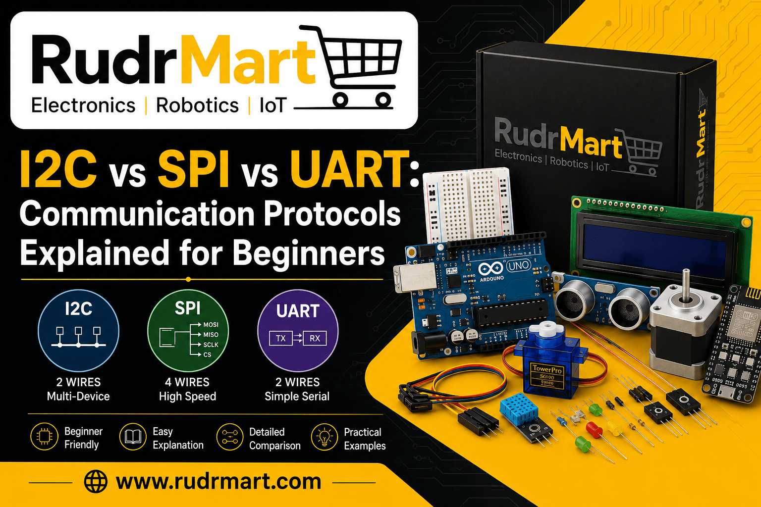
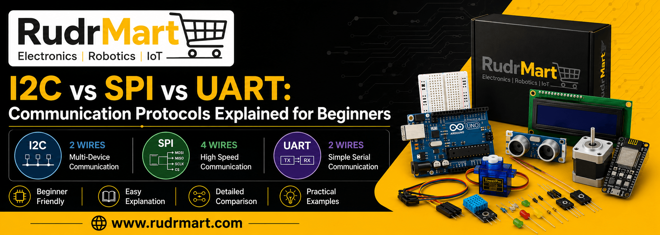
I2C vs SPI vs UART: Which Communication Protocol Should You Use?
When working with Arduino, ESP32, Raspberry Pi, sensors, displays, RFID modules, GPS modules, Bluetooth modules, and other electronic devices, you often need a way for different components to exchange data.
This is where communication protocols come into play. If you’re looking for an easy I2C vs SPI vs UART comparison, this beginner-friendly guide explains how these three communication protocols work, their differences, advantages, pins, speed, and common Arduino applications.
Three of the most commonly used communication methods in electronics and embedded systems are I2C, SPI, and UART. Although all three are used for serial communication, they work differently and are designed for different situations.
If you are a beginner wondering about the I2C vs SPI vs UART difference explained, this guide will help you understand how each protocol works, how many pins it requires, how fast it can communicate, and when you should use it.
In simple terms:
- I2C is excellent when multiple devices need to communicate using only two signal wires.
- SPI is generally preferred when high-speed communication is required.
- UART is simple and commonly used for direct communication between two devices.
Let’s understand the difference between I2C SPI and UART step by step.
What Are Communication Protocols?
A communication protocol is a set of rules that allows electronic devices to exchange information.
For example, imagine that an Arduino is connected to a temperature sensor.
The Arduino needs to ask the sensor:
“What is the current temperature?”
The sensor then sends the temperature value back to the Arduino.
The protocol determines how this information is transmitted, including:
- How data is sent
- How data is received
- Which wires are used
- How devices are identified
- How fast data is transferred
- How devices synchronize communication
- How multiple devices share a connection
This is why understanding microcontroller protocols is important when designing electronics projects.
What Is Serial Communication?
Serial communication means that data is transmitted sequentially, usually one bit at a time, over a communication channel.
Instead of sending many bits simultaneously over multiple wires, serial communication sends data in a sequence.
I2C, SPI, and UART are all commonly used forms of serial communication.
They are widely found in:
- Arduino projects
- ESP32 projects
- Embedded systems
- IoT devices
- Robotics
- Industrial electronics
- Sensors
- Displays
- Communication modules
- Data acquisition systems
However, I2C, SPI, and UART are not interchangeable in every application.
I2C vs SPI vs UART at a Glance
Here is a simple communication protocol comparison table Arduino ESP32 users can use as a starting point.
| Feature | I2C | SPI | UART |
|---|---|---|---|
| Full Name | Inter-Integrated Circuit | Serial Peripheral Interface | Universal Asynchronous Receiver/Transmitter |
| Communication Type | Synchronous | Synchronous | Asynchronous |
| Typical Wires | 2 signal wires | 4 signal wires | 2 signal wires |
| Main Signal Pins | SDA, SCL | MOSI, MISO, SCK, CS | TX, RX |
| Clock Signal | Yes | Yes | No |
| Multiple Devices | Yes | Yes | Usually point-to-point |
| Device Addressing | Yes | Chip Select | No built-in addressing |
| Speed | Moderate | High | Moderate |
| Wiring | Simple | More wires | Very simple |
| Best For | Multiple sensors/displays | High-speed peripherals | Device-to-device communication |
| Common Arduino Uses | LCD, sensors, RTC | RFID, displays, SD cards | Bluetooth, GPS, serial modules |
| Duplex | Half-duplex | Full-duplex | Full-duplex |
The exact maximum speed depends on the hardware, implementation, wiring, and configuration, so these protocols should not be compared only by theoretical speed.
What Is I2C Communication?
I2C communication stands for Inter-Integrated Circuit.
It was designed to allow multiple integrated circuits to communicate using only two main signal lines.
The two primary I2C lines are:
- SDA – Serial Data
- SCL – Serial Clock
This makes I2C particularly useful when you need to connect several sensors or modules without using a large number of microcontroller pins.
SDA and SCL: I2C Pins Explained
The two important I2C pins are:
SDA – Serial Data
SDA carries the actual data between the microcontroller and connected devices.
SCL – Serial Clock
SCL carries the clock signal that synchronizes communication.
Unlike UART, I2C uses a clock signal generated by the controller.
A simplified connection looks like this:
Arduino / ESP32
     │
     ├── SDA ───────── Sensor 1
     │                  │
     │                  ├── Sensor 2
     │                  │
     │                  └── LCD
     │
     └── SCL ───────── Sensor 1
                        │
                        ├── Sensor 2
                        │
                        └── LCD
Multiple compatible devices can share the same SDA and SCL bus, provided their addresses and electrical requirements are handled correctly.
How Does I2C Communication Work?
If you want to understand how does I2C communication work Arduino, think of I2C as a shared communication bus.
One device acts as the controller, while other devices respond to requests.
Each device normally has an I2C address.
For example:
Arduino
   │
   ├── SDA
   └── SCL
       │
       ├── Temperature Sensor – Address 0x48
       ├── OLED Display       – Address 0x3C
       └── RTC Module         – Address 0x68
The Arduino can communicate with the required device by using its address.
This is one of the biggest advantages of I2C.
Advantages of I2C
I2C is popular because it provides several benefits:
- Requires only two main signal lines
- Supports multiple devices
- Devices can share the same bus
- Uses device addresses
- Saves microcontroller GPIO pins
- Excellent for sensors and displays
- Easy to expand
- Widely supported by Arduino and ESP32 libraries
Disadvantages of I2C
I2C also has some limitations:
- Usually slower than SPI
- Requires correct pull-up arrangements
- Bus capacitance can limit performance
- Address conflicts can occur
- Not ideal for very high-speed data transfer
- Longer wiring can cause signal integrity problems
I2C Applications
I2C is commonly used for:
- Temperature sensors
- Pressure sensors
- Accelerometers
- Gyroscopes
- RTC modules
- OLED displays
- LCD displays
- EEPROMs
- ADC/DAC modules
- GPIO expanders
- Environmental sensors
A classic example is an I2C LCD display Arduino connection, where an I2C backpack allows an LCD to communicate with an Arduino using fewer pins.
How LCD I2C Modules Work
Traditional character LCDs can require several Arduino pins for control and data.
An I2C LCD module adds an I2C interface, allowing the Arduino to communicate with the LCD through SDA and SCL.
This significantly reduces the number of GPIO pins required.
This is why I2C LCD modules are extremely popular among Arduino beginners.
What Is SPI Protocol?
SPI stands for Serial Peripheral Interface.
SPI is a synchronous serial communication protocol designed for fast communication between a controller and peripheral devices.
The SPI protocol is widely used in embedded systems because it can provide high-speed data transfer with relatively simple hardware.
SPI generally uses four important signals:
- MOSI
- MISO
- SCK
- CS/SS
MOSI, MISO, SCK and CS: SPI Pins Explained
Understanding these four signals is essential when learning SPI.
MOSI – Master Out, Slave In
MOSI carries data from the controller to the peripheral.
MISO – Master In, Slave Out
MISO carries data from the peripheral back to the controller.
SCK – Serial Clock
SCK provides the clock signal that synchronizes data transfer.
CS/SS – Chip Select / Slave Select
CS selects which peripheral should communicate with the controller.
A simplified SPI connection looks like:
              Arduino
                 │
       ┌─────────┼─────────┐
       │         │         │
      MOSI      MISO      SCK
       │         │         │
       └─────────┼─────────┘
                 │
        ┌────────┴────────┐
        │                 │
      CS 1              CS 2
        │                 │
      RFID              SD Card
MOSI, MISO, and SCK can commonly be shared between SPI peripherals, while each selected peripheral generally requires its own chip-select line.
How Does SPI Communication Work?
If you are asking how does SPI communication work Arduino, the basic process is straightforward.
The Arduino generates a clock signal on SCK.
It sends data through MOSI and receives data through MISO.
The appropriate peripheral is selected using its CS pin.
For example:
Arduino
   │
   ├── MOSI ───────── RFID
   ├── MISO ───────── RFID
   ├── SCK  ───────── RFID
   └── CS   ───────── RFID
For another SPI device:
Arduino
   │
   ├── MOSI ───────── SD Card
   ├── MISO ───────── SD Card
   ├── SCK  ───────── SD Card
   └── CS   ───────── SD Card
The shared SPI lines allow multiple peripherals to use the same bus, while chip-select signals determine which device is active.
Advantages of SPI
SPI has several important advantages:
- High-speed communication
- Full-duplex data transfer
- Simple protocol structure
- No device addressing overhead like I2C
- Excellent for high-data-rate peripherals
- Commonly supported by microcontrollers
- Suitable for displays, memory and RFID modules
Disadvantages of SPI
The main disadvantages include:
- Requires more signal wires
- Additional CS pins are typically needed for multiple devices
- No built-in addressing mechanism
- More GPIO pins may be required
- Wiring can become complicated with many peripherals
SPI Applications
SPI is commonly used with:
- RFID modules
- SD cards
- TFT displays
- Flash memory
- ADCs
- DACs
- High-speed sensors
- Communication modules
- Digital potentiometers
For example, the popular RFID RC522 module commonly communicates with Arduino through SPI.
Understanding RFID RC522 SPI communication is therefore a useful practical example of SPI in Arduino projects.
What Is UART Protocol?
UART stands for Universal Asynchronous Receiver/Transmitter.
UART is one of the simplest methods of serial communication.
Unlike I2C and SPI, UART does not use a separate clock wire.
Instead, both devices agree on communication settings such as:
- Baud rate
- Data bits
- Parity
- Stop bits
The two primary signal lines are:
- TX – Transmit
- RX – Receive
TX and RX: UART Pins Explained
UART communication generally uses:
TX – Transmit
Used to send data from one device.
RX – Receive
Used to receive data by the other device.
The connection is normally crossed:
Device A                 Device B

TX  -------------------> RX
RX  <------------------- TX
GND -------------------- GND
The common ground connection is important so that both devices have a shared voltage reference.
How Does UART Communication Work?
Suppose an Arduino is connected to a Bluetooth module.
The Arduino sends information through TX.
The Bluetooth module receives it through RX.
The Bluetooth module can send information back through its TX line, which connects to the Arduino’s RX line.
Unlike I2C and SPI, there is no shared clock line.
Both devices must use compatible communication settings.
UART Communication Examples
UART is commonly used with:
- Bluetooth modules
- GPS modules
- GSM modules
- Serial displays
- USB-to-serial converters
- Debugging interfaces
- Other microcontrollers
- Industrial serial devices
For example, an HC-05 Bluetooth UART Arduino project commonly uses serial communication between the Arduino and Bluetooth module.
Advantages of UART
UART is popular because it is:
- Simple
- Easy to understand
- Easy to implement
- Requires very few signal wires
- Good for direct device-to-device communication
- Excellent for debugging
- Commonly available on microcontrollers
Disadvantages of UART
UART also has limitations:
- Generally suited to direct device-to-device communication
- No built-in addressing for multiple devices
- Both devices need compatible baud-rate settings
- No shared clock
- Not generally the first choice for connecting many peripherals to one bus
I2C vs SPI vs UART: Main Differences
Now let’s compare the three protocols directly.
1. I2C vs SPI
The biggest difference between I2C vs SPI is how devices are selected and how the bus is structured.
I2C uses:
- SDA
- SCL
- Device addresses
SPI uses:
- MOSI
- MISO
- SCK
- CS
I2C usually requires fewer wires for multiple peripherals.
SPI generally offers higher throughput and simpler high-speed transfers.
Choose I2C when:
- You have multiple sensors
- GPIO pins are limited
- Data rates are moderate
- You want a shared two-wire bus
Choose SPI when:
- Speed is important
- You are transferring large amounts of data
- You are using an RFID reader
- You are using an SD card
- You are using a fast display
2. SPI vs UART
The SPI vs UART comparison is also important.
SPI is synchronous and uses a clock.
UART is asynchronous and does not use a clock line.
SPI is commonly used for communication between a microcontroller and peripherals.
UART is commonly used for communication between two devices.
| Feature | SPI | UART |
| Clock | Yes | No |
| Typical signal lines | MOSI, MISO, SCK, CS | TX, RX |
| Communication | Synchronous | Asynchronous |
| Multiple peripherals | Yes | Not normally through built-in addressing |
| Speed potential | High | Depends on baud rate and hardware |
| Common use | RFID, SD cards, displays | Bluetooth, GPS, debugging |
3. I2C vs UART
I2C and UART are both useful for simple communication, but they solve different problems.
I2C is designed as a shared bus for multiple devices.
UART is generally designed for direct serial communication between devices.
Choose I2C when several peripherals need to communicate with one controller.
Choose UART when you need a simple connection between two devices.
I2C vs SPI Speed Comparison
One of the most common questions beginners ask is:
Which is faster: I2C or SPI?
In many practical implementations, SPI can achieve higher data-transfer rates than I2C.
However, speed is not the only factor you should consider.
For example:
I2C
Good for:
- Sensor readings
- Configuration data
- RTC
- LCD
- Small amounts of data
SPI
Good for:
- High-speed displays
- SD cards
- RFID
- Flash memory
- Large data transfers
The actual speed depends on the specific microcontroller, peripheral, bus configuration, wiring, clock settings, and software.
So rather than simply asking “Which protocol is fastest?”, ask:
“Which protocol provides the right balance of speed, wiring, complexity, and device compatibility for my project?”
I2C SPI UART Pins Explained
Understanding the pins is one of the easiest ways to remember the difference.
| Protocol | Pin | Function |
| I2C | SDA | Data |
| I2C | SCL | Clock |
| SPI | MOSI | Controller → Peripheral data |
| SPI | MISO | Peripheral → Controller data |
| SPI | SCK | Clock |
| SPI | CS/SS | Selects peripheral |
| UART | TX | Transmit |
| UART | RX | Receive |
| UART | GND | Common reference |
I2C vs SPI vs UART for Beginners
If you are new to electronics, use this simple rule:
Use I2C if:
You have multiple sensors or modules and want to save pins.
Example:
Arduino
   │
   ├── Temperature Sensor
   ├── Pressure Sensor
   ├── OLED
   └── RTC
All can potentially share the same I2C bus.
Use SPI if:
You need fast communication with a peripheral.
Example:
Arduino → RFID RC522
Arduino → SD Card
Arduino → TFT Display
Use UART if:
You need simple communication between two devices.
Example:
Arduino ↔ HC-05 Bluetooth
Arduino ↔ GPS
Arduino ↔ USB-Serial
Which Communication Protocol to Use Arduino?
If you’re wondering which communication protocol to use Arduino, start with the device you want to connect.
| Device | Recommended Protocol |
| I2C LCD | I2C |
| OLED Display | I2C or SPI, depending on module |
| Temperature Sensor | Often I2C |
| Accelerometer | I2C or SPI |
| RFID RC522 | SPI |
| SD Card | SPI |
| HC-05 Bluetooth | UART |
| GPS Module | UART |
| Serial Debugging | UART |
| RTC Module | I2C |
| High-speed TFT | Often SPI |
| EEPROM | Often I2C or SPI |
Always check the specific module’s datasheet because some devices support more than one interface.
Best Communication Protocol for Sensors Arduino
For many Arduino sensor projects, I2C is an excellent choice.
Why?
Because sensors often transfer relatively small amounts of data, and multiple sensors can share the same two-wire bus.
For example:
Arduino
   │
   ├── SDA ── Temperature Sensor
   │
   ├── SDA ── Pressure Sensor
   │
   ├── SDA ── Accelerometer
   │
   └── SDA ── OLED
The same SCL line is shared as well.
However, SPI can be preferable when a sensor requires higher data rates or when the sensor specifically recommends SPI.
Therefore, the best communication protocol for sensors Arduino projects depends on the sensor, speed requirements, number of devices, available pins, and wiring distance.
UART vs I2C vs SPI Use Cases
Here’s another simple way to remember their common use cases.
I2C
Think:
“Many devices, fewer wires.”
Typical examples:
- Sensors
- LCDs
- OLEDs
- RTC
- EEPROM
SPI
Think:
“High-speed peripheral communication.”
Typical examples:
- RFID
- SD cards
- TFT displays
- Flash memory
UART
Think:
“Simple device-to-device serial communication.”
Typical examples:
- Bluetooth
- GPS
- GSM
- Serial debugging
Serial Communication Protocols in Embedded Systems
In embedded systems, selecting the correct communication protocol can have a major impact on system design.
Engineers typically consider:
- Data rate
- Number of devices
- Number of available GPIO pins
- Communication distance
- Power consumption
- Hardware support
- Software support
- Noise environment
- Timing requirements
- System complexity
I2C, SPI, and UART are therefore fundamental parts of embedded communication.
They are found in everything from simple Arduino projects to more advanced industrial and IoT systems.
I2C vs SPI vs UART: Real-World Example
Imagine you are building an Arduino-based environmental monitoring system.
You want:
- Temperature sensor
- Humidity sensor
- OLED display
- SD card
- Bluetooth module
A practical architecture might look like:
                    Arduino
                       │
        ┌──────────────┼──────────────┐
        │              │              │
       I2C            SPI            UART
        │              │              │
   ┌────┴────┐     ┌───┴───┐       Bluetooth
   │         │     │       │
 Temp      OLED   SD Card  Other
 Sensor            RFID
Here:
- I2C handles sensors and display
- SPI handles high-speed peripherals
- UART handles Bluetooth
This demonstrates an important point:
You don’t have to choose only one communication protocol for an entire project.
A single microcontroller can use I2C, SPI, and UART simultaneously.
Can Arduino Use I2C, SPI and UART at the Same Time?
Yes.
Many Arduino-compatible boards provide hardware support for multiple communication interfaces.
For example, a project could use:
I2C  → OLED + Sensors
SPI  → RFID + SD Card
UART → Bluetooth
This allows each device to use the communication method best suited to its requirements.
The exact available pins and peripheral instances depend on the Arduino board or microcontroller being used.
I2C vs SPI vs UART: Advantages Comparison
| Feature | I2C | SPI | UART |
| Easy for beginners | ⭐⭐⭐⭐ | ⭐⭐⭐⭐ | ⭐⭐⭐⭐⭐ |
| Low pin count | ⭐⭐⭐⭐⭐ | ⭐⭐⭐ | ⭐⭐⭐⭐⭐ |
| High speed | ⭐⭐⭐ | ⭐⭐⭐⭐⭐ | ⭐⭐⭐ |
| Multiple peripherals | ⭐⭐⭐⭐⭐ | ⭐⭐⭐⭐ | ⭐⭐ |
| Simple wiring | ⭐⭐⭐⭐⭐ | ⭐⭐⭐ | ⭐⭐⭐⭐⭐ |
| Device addressing | Yes | CS-based selection | No built-in addressing |
| Clock required | Yes | Yes | No |
| Common Arduino applications | Sensors/displays | RFID/SD/display | Bluetooth/GPS |
Common Beginner Mistakes
When learning communication protocols, beginners often make a few common mistakes.
1. Connecting TX to TX
For UART, the usual connection is:
TX → RX
RX → TX
Not:
TX → TX
RX → RX
2. Forgetting Common Ground
Devices generally need a common electrical reference.
Always check whether the modules require:
GND ↔ GND3. Using the Wrong I2C Pins
I2C SDA and SCL pins depend on the specific Arduino or ESP32 board.
Always check the board documentation or pinout.
4. Forgetting SPI Chip Select
With SPI, the correct CS pin must be configured for the selected peripheral.
5. Ignoring Voltage Levels
Different boards and modules may use different logic voltage levels.
For example, a 5 V Arduino and a 3.3 V peripheral may require careful consideration of logic-level compatibility.
Always check the module’s electrical specifications before connecting it.
6. Ignoring I2C Address Conflicts
Two I2C devices cannot normally use the same address on the same bus unless the hardware provides a way to change or isolate the address.
How to Choose Between I2C, SPI and UART
Use this simple decision tree.
Question 1: Do you need to connect multiple peripherals?
Yes → Consider I2C or SPI.
Question 2: Is high-speed data transfer important?
Yes → Consider SPI.
Question 3: Are you connecting one device directly to another?
Yes → UART may be the simplest option.
Question 4: Are you connecting several low-to-moderate speed sensors?
Yes → I2C is often a good choice.
Question 5: Does the module specify a required interface?
Yes → Follow the module’s datasheet.
The device’s supported interface should always take priority over a general rule.
I2C vs SPI vs UART: Which One Is Better?
There is no universally “best” protocol.
Each protocol is optimized for different requirements.
I2C is better when:
- You need multiple devices
- You want fewer signal wires
- Your data rate requirements are moderate
- You are working with sensors and displays
SPI is better when:
- High speed is important
- You need full-duplex communication
- You are working with SD cards or RFID
- You need fast display or memory communication
UART is better when:
- You need simple point-to-point communication
- You are connecting Bluetooth or GPS
- You need serial debugging
- You want a simple interface with few signal wires
I2C vs SPI vs UART Cheat Sheet
Remember these three simple phrases:
I2C
Two-wire bus for multiple devices.
SDA + SCLSPI
Fast synchronous communication.
MOSI + MISO + SCK + CSUART
Simple asynchronous device-to-device communication.
TX + RXIf you remember these three concepts, you already understand the basic difference between I2C, SPI, and UART.
Practical Arduino Communication Examples
The best way to understand these protocols is by using them in real projects.
I2C LCD Display Arduino Connection
An I2C LCD can reduce the number of Arduino pins needed compared with a traditional parallel LCD connection.
Typical connections include:
LCD I2C Module → Arduino
SDA             → SDA
SCL             → SCL
VCC             → VCC
GND             → GND
This is a great beginner project for understanding I2C communication.
RFID RC522 SPI Communication
The RC522 RFID module is a popular Arduino project component.
It commonly communicates through SPI using:
MOSI
MISO
SCK
SS/CS
This makes the RC522 a useful example for learning the SPI protocol.
HC-05 Bluetooth UART Arduino
An HC-05 Bluetooth module commonly communicates through serial UART.
The basic concept is:
Arduino TX → HC-05 RX
Arduino RX ← HC-05 TX
GND        ↔ GND
This is a practical example of UART communication.
Quick Final Comparison
| Requirement | Best Starting Choice |
| Multiple sensors | I2C |
| I2C LCD | I2C |
| OLED | I2C or SPI |
| RFID RC522 | SPI |
| SD Card | SPI |
| High-speed peripheral | SPI |
| Bluetooth HC-05 | UART |
| GPS module | UART |
| Serial debugging | UART |
| Few GPIO pins | I2C |
| Multiple peripherals on a shared bus | I2C/SPI |
| Simple two-device connection | UART |
In short: choose I2C for simplicity and multiple low-to-moderate speed peripherals, SPI for higher-speed peripherals, and UART for straightforward serial device-to-device communication.
Conclusion
Understanding I2C vs SPI vs UART is an essential step for anyone learning Arduino, ESP32, embedded systems, or electronics.
All three are serial communication protocols, but each has a different purpose.
I2C is ideal for connecting multiple sensors, displays, and other peripherals while keeping the number of signal wires low.
SPI is generally the better choice when high-speed communication is required, especially for devices such as RFID readers, SD cards, displays, and memory.
UART is a simple and reliable option for direct communication between devices such as Arduino boards, Bluetooth modules, GPS modules, and serial interfaces.
The easiest way to remember the difference is:
I2C = Multiple devices with fewer wires
SPI = High-speed peripheral communication
UART = Simple device-to-device serial communication
When choosing a protocol, don’t select one simply because it is “faster.” Consider the number of devices, required speed, available pins, wiring, voltage levels, software support, and the interface supported by your peripheral.
Once you understand these fundamentals, working with Arduino communication, microcontroller protocols, and embedded communication becomes much easier.
Frequently Asked Questions
1. Is I2C faster than UART?
Not necessarily.
Actual performance depends on the configured bus speed, hardware, implementation, and data format. I2C and UART are designed differently and are typically chosen for different use cases.
2. Is SPI faster than I2C?
SPI can generally support higher clock rates and higher throughput than I2C in many implementations.
However, actual performance depends on the hardware and configuration.
3. Which is easier: I2C, SPI or UART?
UART is often the easiest protocol for beginners to understand because it uses simple TX and RX connections and does not require a clock line.
I2C is also beginner-friendly once you understand SDA, SCL, and device addresses.
4. Can multiple devices use I2C?
Yes. Multiple compatible devices can share the I2C bus using their device addresses.
5. Can multiple devices use SPI?
Yes. SPI devices can share MOSI, MISO, and SCK, while separate chip-select signals are generally used to select individual peripherals.
6. Does UART need a clock wire?
No.
UART is asynchronous and does not use a separate clock signal
7. What are the I2C pins?
The main I2C pins are:
- SDA – Serial Data
- SCL – Serial Clock
The physical Arduino pins depend on the board.
8. What are the SPI pins?
The main SPI signals are:
- MOSI
- MISO
- SCK
- CS/SS
The physical pins depend on the microcontroller or development board.
9. What are UART pins?
The primary UART communication pins are:
- TX – Transmit
- RX – Receive
A common ground is also normally required.
10. Can Arduino use all three protocols?
Yes. Depending on the board and available hardware peripherals, Arduino projects can use I2C, SPI, and UART simultaneously.
11. Is I2C or SPI better for sensors?
Both can be excellent.
I2C is particularly convenient when you have multiple sensors and want to minimize wiring.
SPI may be better when a sensor requires higher data rates.
Always check the sensor’s datasheet.
Arduino CommunicationArduino TutorialsCommunication ProtocolsEmbedded SystemsESP32I2CI2C CommunicationI2C vs SPII2C vs SPI vs UARTSerial CommunicationSPISPI ProtocolUARTUART Protocol