- Empty cart.
- Continue Shopping
PIR Motion Sensor + Buzzer: Build a Simple Arduino Security Alarm
- Posted on
 Deepak Joshi
- 0
- Categories: Arduino Projects

Introduction
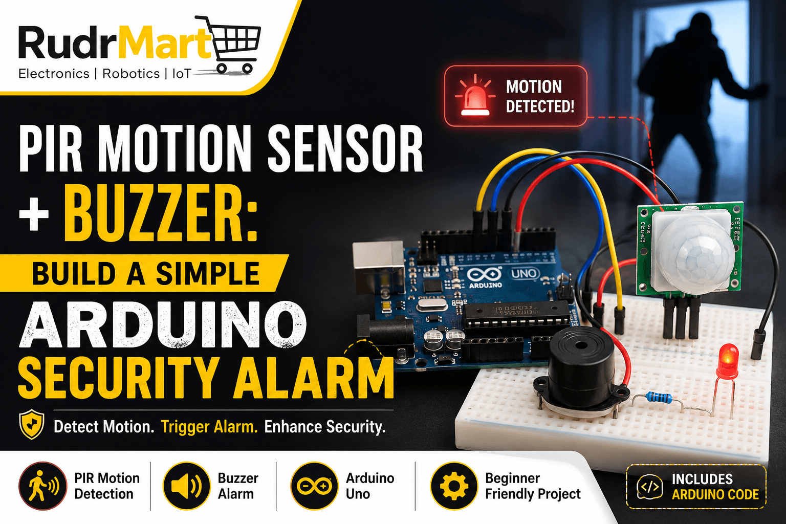
PIR motion sensor Arduino projects are a great way to learn how sensors, microcontrollers, and alarms work together. In this project, we will use an Arduino Uno, HC-SR501 PIR motion sensor, buzzer, and LED to build a simple motion-activated security alarm.
This PIR sensor Arduino project is beginner-friendly and demonstrates how an Arduino can detect movement and trigger an audible alarm. The HC-SR501 detects changes in infrared radiation caused by movement, while the Arduino processes the sensor signal and activates the buzzer.
If you are searching for how to make a security alarm using Arduino, this project provides the wiring, code, working principle, and step-by-step instructions you need to get started.
What Is a PIR Motion Sensor?
A PIR motion sensor is a Passive Infrared sensor that detects changes in infrared radiation. Objects such as people and animals emit infrared energy, and the sensor detects changes when they move through its detection area.
In a PIR motion sensor Arduino project, the PIR module provides a digital signal to the Arduino. The Arduino then decides what action to take, such as switching on an LED or activating a buzzer.
PIR sensors are commonly used for motion detection because they are relatively inexpensive, low-power, and easy to interface with microcontrollers. Adafruit’s PIR documentation explains that the sensor detects changes in infrared radiation rather than simply measuring an object’s average infrared level.
How Does a PIR Motion Sensor Arduino System Work?
The basic working principle is straightforward:
Movement → PIR Sensor → Arduino → Buzzer + LED
When a person moves within the detection area, the HC-SR501 PIR sensor detects the change in infrared radiation.
The sensor output changes state, and the Arduino reads this signal through a digital input.
If the Arduino detects a HIGH signal, it activates the buzzer and LED.
This simple process makes a PIR motion sensor Arduino project an excellent introduction to sensor-based automation.
PIR Sensor Working Principle and Arduino Interfacing
A PIR sensor contains a pyroelectric sensing element that responds to changes in infrared radiation. A moving warm object can create a differential change across the sensing elements, which is then processed into a digital output signal.
For a beginner motion sensor Arduino project, you do not need to process the infrared signal yourself. The HC-SR501 module handles the sensor processing and provides a digital output to the Arduino.
Why Use PIR Sensor Arduino Projects?
A PIR sensor Arduino setup is particularly useful for beginners because it requires only a few components and simple programming.
With an Arduino Uno and HC-SR501, you can create:
- Arduino security alarm
- Motion detector alarm
- DIY burglar alarm
- Motion-activated LED
- Arduino home security prototype
- Motion-triggered buzzer
- Basic automation system
Components Required
To build this Arduino security alarm, you will need:
| Component | Quantity |
|---|---|
| Arduino Uno | 1 |
| HC-SR501 PIR motion sensor | 1 |
| Buzzer | 1 |
| LED | 1 |
| 220Ω resistor | 1 |
| Breadboard | 1 |
| Jumper wires | As required |
| USB cable | 1 |
| Arduino IDE | 1 |
The Arduino Uno is particularly suitable for beginners. Arduino describes the UNO R3 as a board designed for getting started with electronics and coding, with 14 digital input/output pins and 6 analog inputs.
For more information, you can refer to the official Arduino UNO R3 documentation.
How to Make a Security Alarm Using Arduino
The basic idea behind this project is simple.
The HC-SR501 PIR sensor is connected to a digital input pin of the Arduino. The buzzer is connected to a digital output pin.
When no movement is detected, the buzzer remains OFF.
When the PIR sensor detects movement, its output becomes HIGH. The Arduino reads this signal and turns the buzzer ON.
You can also connect an LED so that both the LED and buzzer activate when motion is detected.
This creates a simple Arduino based home security system for beginners.
How to Connect PIR Sensor to Arduino
The HC-SR501 normally has three pins:
| HC-SR501 Pin | Arduino Connection |
|---|---|
| VCC | 5V |
| OUT | Digital Pin 2 |
| GND | GND |
For the buzzer:
| Buzzer Pin | Arduino Connection |
| Positive (+) | Digital Pin 8 |
| Negative (-) | GND |
For the optional LED:
| LED Connection | Arduino |
| Anode (+) | Digital Pin 13 through 220Ω resistor |
| Cathode (-) | GND |
The Arduino Uno is a popular beginner-friendly development board. You can find its official specifications, pinout, and technical documentation on the Arduino UNO R3 official documentation.
Simple Connection Diagram
HC-SR501 → Arduino
HC-SR501 PIR Sensor
--------------------
VCC  → Arduino 5V
OUT  → Arduino D2
GND  → Arduino GND

Buzzer
--------------------
+    → Arduino D8
-    → Arduino GND

LED
--------------------
Anode   → D13 through 220Ω resistor
Cathode → GND
This is the basic Arduino motion detector alarm circuit.
Understanding the HC-SR501 PIR Sensor
Before programming the project, it is useful to understand the main controls available on the HC-SR501.
Most HC-SR501 modules have two adjustment potentiometers and a trigger-mode jumper.
1. Sensitivity Adjustment
The sensitivity control determines the approximate detection range of the PIR sensor.
Depending on the module and environment, the sensor can typically detect movement several metres away.
2. Time Delay Adjustment
The time-delay control determines how long the sensor output remains HIGH after detecting movement.
This allows you to control how long the alarm stays active.
3. Trigger Mode
The jumper generally provides two trigger modes:
H – Repeatable Trigger
The output can remain active or be retriggered while movement continues.
L – Single Trigger
The output remains active for the configured period and then returns LOW.
For a simple motion sensor buzzer alarm project Arduino setup, the repeatable mode can be useful when you want continuous movement to keep the alarm active.
Arduino Code for Motion-Activated Alarm
Below is a simple Arduino PIR sensor code example for the HC-SR501.
const int pirPin = 2;
const int buzzerPin = 8;
const int ledPin = 13;

void setup() {
  pinMode(pirPin, INPUT);
  pinMode(buzzerPin, OUTPUT);
  pinMode(ledPin, OUTPUT);

  digitalWrite(buzzerPin, LOW);
  digitalWrite(ledPin, LOW);

  Serial.begin(9600);
}

void loop() {

  int motion = digitalRead(pirPin);

  if (motion == HIGH) {
    digitalWrite(buzzerPin, HIGH);
    digitalWrite(ledPin, HIGH);

    Serial.println("Motion Detected!");
  }
  else {
    digitalWrite(buzzerPin, LOW);
    digitalWrite(ledPin, LOW);

    Serial.println("No Motion");
  }

  delay(100);
}
How the Code Works
The program first defines the pins connected to the PIR sensor, buzzer, and LED.
const int pirPin = 2;The PIR sensor output is connected to digital pin 2.
The buzzer is connected to:
const int buzzerPin = 8;During the loop(), Arduino continuously reads the PIR sensor:
int motion = digitalRead(pirPin);If the sensor output is HIGH, movement has been detected.
The Arduino then activates the buzzer and LED:
digitalWrite(buzzerPin, HIGH);
digitalWrite(ledPin, HIGH);
When the sensor output returns LOW, the buzzer and LED are switched OFF.
How the Arduino Security Alarm Works
Once the circuit is powered and the code is uploaded, the PIR sensor needs a short period to stabilize.
After stabilization, the system continuously monitors the sensor output.
When No Movement Is Detected
The PIR output is LOW.
Arduino → Buzzer OFF → LED OFF
When Movement Is Detected
The PIR output becomes HIGH.
Arduino → Buzzer ON → LED ON
The buzzer alerts anyone nearby that movement has been detected.
This simple mechanism makes the project a functional simple burglar alarm using Arduino and PIR sensor.
PIR Sensor Calibration
One important step that beginners sometimes overlook is PIR sensor calibration.
After powering the HC-SR501, allow it some time to stabilize before testing the alarm.
The sensor’s sensitivity and delay controls can then be adjusted according to your requirements.
For example:
- Increase sensitivity if the detection range is too short.
- Reduce sensitivity if false alarms occur frequently.
- Adjust the time delay to determine how long the alarm remains active.
- Test the sensor from different distances and directions.
Keep in mind that PIR sensors detect changes in infrared radiation, so environmental conditions can affect performance.
Testing the Motion Sensor Arduino Project
Follow these steps to test your project:
Step 1: Assemble the Circuit
Connect the HC-SR501, Arduino, buzzer, and optional LED according to the wiring table.
Step 2: Upload the Code
Connect the Arduino to your computer and upload the program using the Arduino IDE.
Step 3: Allow the Sensor to Stabilize
After powering the system, wait for the PIR sensor to initialize.
Step 4: Walk in Front of the Sensor
Move across the sensor’s detection area.
The sensor should detect your movement.
Step 5: Check the Alarm
When motion is detected, the buzzer should turn ON and the LED should illuminate.
Congratulations—you have built a basic Arduino alarm system.
Common Problems and Solutions
PIR Sensor Is Not Detecting Motion
Check the following:
- Confirm that VCC is connected to 5V.
- Confirm that GND is connected correctly.
- Check that the OUT pin is connected to Arduino digital pin 2.
- Allow the HC-SR501 to stabilize after power-up.
- Adjust the sensitivity control.
- Make sure the sensor has a clear field of view.
Buzzer Is Not Working
Check whether the buzzer is connected with the correct polarity.
Also confirm that the Arduino pin number in the code matches the physical connection.
For example:
const int buzzerPin = 8;means the buzzer must be connected to digital pin 8.
Alarm Stays ON
This may be caused by the PIR sensor’s time-delay setting or trigger mode.
Adjust the delay potentiometer and check the trigger-mode jumper.
False Alarms
False triggers can sometimes occur due to environmental changes.
Avoid placing the PIR sensor directly near:
- Heaters
- Air conditioners
- Direct sunlight
- Strong heat sources
- Rapid temperature changes
Arduino Motion Sensor Project With LED and Buzzer
Adding an LED makes the project easier to understand because you get both visual and audible feedback.
When motion is detected:
PIR → Arduino → LED ON + Buzzer ON
When motion stops:
PIR → Arduino → LED OFF + Buzzer OFF
This makes the project a useful introduction to combining sensors with multiple outputs.
You can further expand the project by adding:
- LCD display
- Relay module
- GSM module
- Wi-Fi module
- ESP8266 or ESP32
- Camera module
- Magnetic door sensor
- Keypad
- Mobile notifications
These additions can transform a basic PIR sensor Arduino experiment into a more advanced security system.
How to Improve the Arduino Alarm System
The basic circuit is intentionally simple, but there are several ways to make it more useful.
Add an Alarm Delay
You can program the Arduino to activate the alarm only after motion has been detected for a specific amount of time.
Add an Alarm Timer
Instead of keeping the buzzer active while motion is detected, you can program the buzzer to remain active for a fixed period.
Add a Password System
A keypad can be added so that the alarm can be armed or disarmed using a password.
Add Wireless Notifications
An ESP8266, ESP32, or GSM module can send a notification when motion is detected.
Add a Relay
A relay can be used to control another compatible electrical device. Proper electrical safety precautions should always be followed when working with mains voltage.
Applications of a PIR Motion Sensor With Arduino and Buzzer
This project can be adapted for several educational and prototype applications.
Home Security
Use the PIR sensor to detect movement in a room, entrance, garage, or storage area.
Doorway Monitoring
Position the sensor near an entrance to create a basic movement alert.
Office Security
The system can be used as a simple after-hours motion detector prototype.
Electronics Learning
Students and beginners can use the project to learn:
- Digital input
- Digital output
- Sensor interfacing
- Arduino programming
- Conditional statements
- Buzzer control
- Basic security automation
PIR Motion Sensor vs. Other Motion Sensors
PIR sensors are particularly useful for beginner projects because they are inexpensive and relatively easy to interface.
However, different applications may require different sensing technologies.
| Sensor Type | Common Use |
| PIR | Human/animal movement detection |
| Ultrasonic | Distance and object detection |
| Microwave | Motion detection |
| IR obstacle sensor | Short-range object detection |
For a beginner-friendly Arduino motion detector alarm circuit, the HC-SR501 is a practical choice.
Why Use HC-SR501 With Arduino?
The HC-SR501 is popular in DIY electronics because it offers:
- Simple three-pin interface
- Adjustable sensitivity
- Adjustable delay
- Selectable trigger modes
- Digital output
- Easy Arduino integration
- Low-cost implementation
Its straightforward interface makes it ideal for learning how to connect PIR sensor to Arduino.
Safety Considerations
This project operates at low voltage and is suitable for basic electronics experimentation.
However, do not connect the Arduino directly to high-voltage AC appliances.
If you want to control mains-powered equipment using a relay, use an appropriately rated relay module, proper insulation, enclosure, fusing, earthing, and safe wiring practices. If you are not experienced with mains electricity, have the installation handled by a qualified professional.
Also remember that a DIY Arduino alarm should be considered a prototype or supplementary security device, not a replacement for a professionally installed security system where high security is required.
Conclusion
Building a PIR Motion Sensor + Buzzer Arduino security alarm is a simple and practical way to learn how sensors and microcontrollers work together.
Using just an Arduino Uno, HC-SR501 PIR motion sensor, buzzer, and a few wires, you can create a basic motion-activated alarm. The Arduino continuously monitors the PIR sensor and activates the buzzer whenever movement is detected.
The project can also serve as a foundation for more advanced systems involving Wi-Fi notifications, cameras, keypads, relays, displays, and other sensors.
For beginners, this PIR motion sensor with Arduino and buzzer project is an excellent introduction to Arduino-based security and automation.
Frequently Asked Questions
1. What is a PIR sensor in Arduino?
A PIR sensor is a Passive Infrared sensor that detects changes in infrared radiation caused by moving objects, particularly people and animals. Arduino can read the sensor’s digital output and respond accordingly.
2. Can I connect an HC-SR501 directly to Arduino?
Yes. The HC-SR501 typically has VCC, GND, and OUT pins. VCC can be connected to Arduino 5V, GND to Arduino GND, and OUT to a digital input pin.
3. How do I make a security alarm using Arduino?
Connect an HC-SR501 PIR sensor to an Arduino digital input and a buzzer to a digital output. Program the Arduino to activate the buzzer whenever the PIR output becomes HIGH.
4. What is the best Arduino board for this project?
Arduino Uno is an excellent choice for beginners because it is easy to program, widely supported, and provides enough digital pins for a basic alarm.
5. Does the PIR sensor detect a stationary person?
A PIR sensor primarily detects changes in infrared radiation. If a person remains completely still for an extended period, the sensor may eventually stop detecting movement.
6. How far can the HC-SR501 detect movement?
The detection range depends on the module’s configuration, environment, and sensitivity setting. The HC-SR501 is generally intended for several metres of motion detection rather than precision distance measurement.
Arduino Buzzer ProjectArduino Home SecurityArduino Motion DetectorArduino ProjectsArduino Security AlarmArduino UnoHC-SR501Motion Sensor ArduinoPIR Motion SensorPIR Sensor ArduinoRudr Martrudrmart