- Empty cart.
- Continue Shopping
How to Build an RFID Door Lock System Using Arduino & RC522 (Complete Guide)
- Posted on
 Deepak Joshi
- 0
- Categories: Arduino Projects

Introduction
Imagine unlocking your room, office, or cabinet with just an RFID card instead of a traditional key. An RFID door lock system offers a secure, fast, and contactless way to control access. Moreover, it is one of the most popular Arduino projects for beginners and electronics enthusiasts.
In this guide, you’ll learn how to build an RFID Door Lock System Using Arduino & RC522 from scratch. We will cover the required components, circuit connections, Arduino code, working principle, troubleshooting tips, and future upgrades.
Whether you’re a student working on a college project or a hobbyist learning embedded systems, this project is simple, affordable, and practical.
What is an RFID Door Lock System?
An RFID Door Lock System is an electronic access control system that unlocks a door only when an authorized RFID card or RFID key tag is presented.
Instead of using mechanical keys, the system verifies the unique ID stored inside an RFID card. If the card matches the authorized IDs programmed into the Arduino, the door lock opens for a few seconds.
Otherwise, access is denied.
This project is widely used for:
- Home security
- Office access
- Laboratory doors
- College projects
- Smart lockers
- Attendance systems
What is RFID?
RFID stands for Radio Frequency Identification.
It is a wireless technology that identifies objects using radio waves.
An RFID system consists of:
- RFID Reader
- RFID Card or Tag
- Microcontroller (Arduino)
- Electronic Lock
When the RFID tag comes near the reader, it sends its unique identification number. The Arduino compares this number with stored authorized IDs.
If the UID matches, the lock opens.
How RFID Technology Works
The working process is straightforward.
Step 1
Power is supplied to the Arduino and RC522 module.
Step 2
The RC522 continuously scans for RFID cards.
Step 3
When a card comes close, the reader reads its UID.
Step 4
Arduino compares the UID with stored IDs.
Step 5
If the UID matches:
- Relay activates
- Solenoid lock unlocks
- Green LED glows
- Buzzer beeps once
Step 6
If the UID does not match:
- Door remains locked
- Red LED glows
- Buzzer beeps multiple times
Components Required
| Component | Quantity |
|---|---|
| Arduino UNO | 1 |
| RC522 RFID Module | 1 |
| RFID Card or Key Tag | 1–2 |
| Relay Module | 1 |
| Solenoid Door Lock (12V) | 1 |
| 12V Adapter | 1 |
| Breadboard | 1 |
| Jumper Wires | Several |
| Green LED | 1 |
| Red LED | 1 |
| 220Ω Resistors | 2 |
| Buzzer | 1 |
Understanding the RC522 RFID Module
The RC522 is one of the most popular RFID readers for Arduino projects.
Features
- Operating Voltage: 3.3V
- Frequency: 13.56 MHz
- SPI Communication
- Reading Distance: 2–5 cm
- Low Power Consumption
- Fast Reading Speed
Arduino RC522 Pin Connections
| RC522 Pin | Arduino UNO |
|---|---|
| SDA | D10 |
| SCK | D13 |
| MOSI | D11 |
| MISO | D12 |
| IRQ | Not Connected |
| GND | GND |
| RST | D9 |
| 3.3V | 3.3V |
Relay Connections
| Relay Pin | Arduino |
|---|---|
| IN | D7 |
| VCC | 5V |
| GND | GND |
LED Connections
Green LED
Positive → D5
Negative → GND through 220Ω resistor
Red LED
Positive → D6
Negative → GND through 220Ω resistor
Buzzer Connection
Positive → D4
Negative → GND
Solenoid Lock Connection
The relay acts like a switch between the power supply and the solenoid lock.
When the relay turns ON, the lock receives 12V power and unlocks.
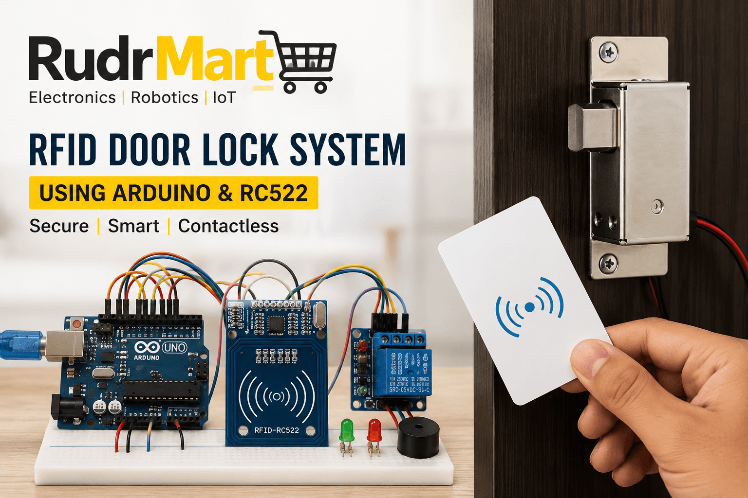
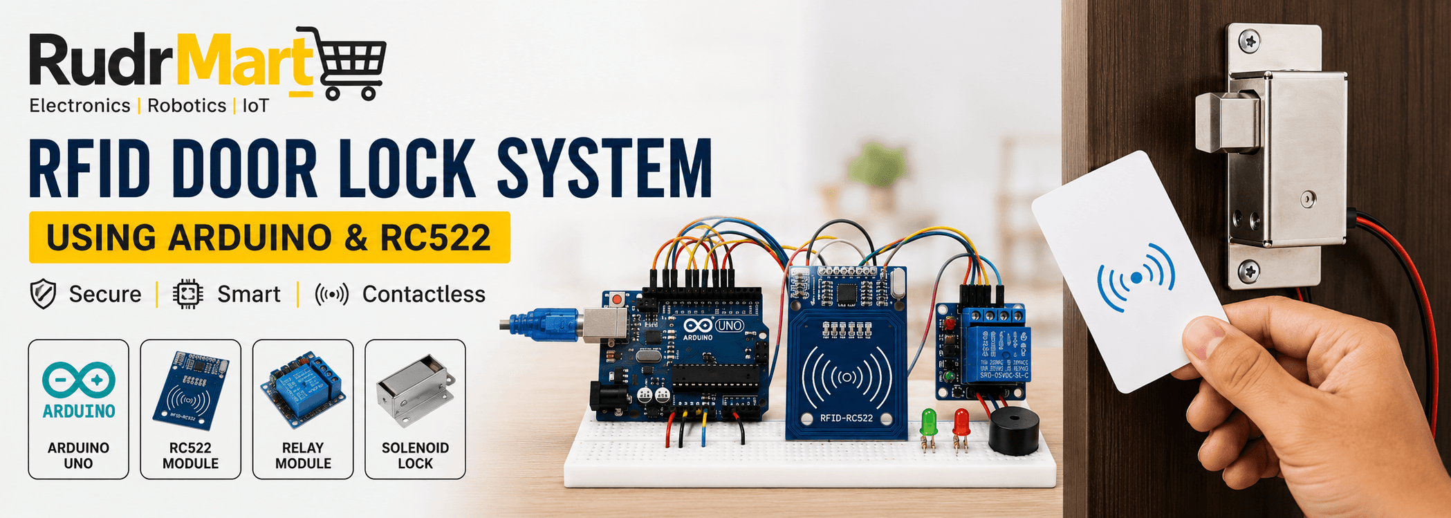
Circuit Diagram Overview
The complete system consists of:
- Arduino UNO as the controller
- RC522 for reading RFID cards
- Relay module for switching the lock
- Solenoid lock for physical locking
- LEDs for status indication
- Buzzer for audio feedback
Arduino Code
</ > C++
#include <SPI.h>
#include <MFRC522.h>

#define SS_PIN 10
#define RST_PIN 9

MFRC522 rfid(SS_PIN, RST_PIN);

int relay = 7;
int greenLED = 5;
int redLED = 6;
int buzzer = 4;

byte authorizedUID[] = {0xDE,0xAD,0xBE,0xEF};

void setup()
{
  SPI.begin();
  rfid.PCD_Init();

  pinMode(relay,OUTPUT);
  pinMode(greenLED,OUTPUT);
  pinMode(redLED,OUTPUT);
  pinMode(buzzer,OUTPUT);

  digitalWrite(relay,LOW);

  Serial.begin(9600);
}

void loop()
{
  if(!rfid.PICC_IsNewCardPresent())
    return;

  if(!rfid.PICC_ReadCardSerial())
    return;

  bool authorized = true;

  for(byte i=0;i<4;i++)
  {
    if(rfid.uid.uidByte[i]!=authorizedUID[i])
      authorized=false;
  }

  if(authorized)
  {
    digitalWrite(relay,HIGH);
    digitalWrite(greenLED,HIGH);
    tone(buzzer,1000);
    delay(300);
    noTone(buzzer);

    delay(5000);

    digitalWrite(relay,LOW);
    digitalWrite(greenLED,LOW);
  }
  else
  {
    digitalWrite(redLED,HIGH);

    tone(buzzer,500);

    delay(1000);

    noTone(buzzer);

    digitalWrite(redLED,LOW);
  }

  rfid.PICC_HaltA();
}
Required Arduino Libraries
Install these libraries before uploading the code.
- SPI Library
- MFRC522 Library
You can install the MFRC522 library from the Arduino Library Manager.
How to Upload the Code
Follow these steps carefully.
- Install Arduino IDE.
- Connect Arduino using a USB cable.
- Install the MFRC522 library.
- Paste the code.
- Select the correct board.
- Select the correct COM port.
- Upload the code.
- Open Serial Monitor.
- Scan the RFID card.
- Replace the sample UID in the code with your own card UID.
- Upload the updated code again.
Testing the RFID Door Lock
After uploading the code:
- Power the Arduino.
- Bring the RFID card close to the RC522.
- If the UID matches, the relay activates.
- The solenoid unlocks.
- Green LED turns ON.
- Buzzer sounds.
- After five seconds, the door locks automatically.
If the card is unauthorized:
- Red LED turns ON.
- Buzzer alerts.
- Door remains locked.
Applications
This project can be used in many real-world situations.
Home Security
Replace traditional keys with RFID cards.
Office Access
Allow employees to enter authorized areas.
School Laboratories
Restrict access to expensive equipment.
Smart Cabinets
Protect valuable items.
Hotel Rooms
Control room access.
Attendance Systems
Track employee or student attendance.
Advantages of RFID Door Lock Systems
There are several reasons why RFID access systems are becoming increasingly popular.
- Contactless operation
- Fast authentication
- Easy to use
- Low maintenance
- High reliability
- Better security than ordinary locks
- Expandable for multiple users
- Affordable DIY project
Common Problems and Solutions
RFID Card Not Detected
Possible Causes
- Loose wires
- Wrong voltage
- Incorrect SPI connections
Solution
Check all wiring and ensure the RC522 is powered with 3.3V, not 5V.
Relay Does Not Activate
Solution
Verify the relay pin number in the code and ensure the relay module receives 5V power.
Solenoid Lock Does Not Unlock
Solution
Ensure the 12V adapter can provide enough current and that the relay wiring is correct.
Wrong UID
Solution
Use the Serial Monitor to read the RFID card’s UID and update it in the Arduino code.
Future Improvements
You can make this project more advanced by adding additional features.
- LCD display
- OLED display
- ESP32 Wi-Fi control
- Mobile app integration
- Fingerprint authentication
- Face recognition
- Cloud logging
- Password keypad
- GSM notifications
- Automatic attendance recording
- Time-based access control
Safety Tips
While building the project, follow these precautions.
- Do not power the RC522 with 5V.
- Use a separate 12V supply for the solenoid lock.
- Check all wiring before switching on the power.
- Insulate exposed wires.
- Test on a breadboard before permanent installation.
Conclusion
Building an RFID Door Lock System Using Arduino & RC522 is an excellent way to learn about RFID technology, SPI communication, and embedded system design. The project combines hardware and software concepts while offering a practical solution for access control.
Furthermore, it provides a solid foundation for advanced IoT and smart security projects. Once you have mastered the basic version, you can enhance it with Wi-Fi connectivity, cloud monitoring, mobile app integration, or biometric authentication.
If you’re looking for quality Arduino boards, RFID modules, relay modules, solenoid locks, jumper wires, and other electronics components, explore RudrMart’s extensive collection to get everything you need for your next DIY project.
Frequently Asked Questions (FAQs)
1. Can RC522 work with Arduino Nano?
Yes. The RC522 works with Arduino UNO, Nano, Mega, and other compatible boards using SPI communication.
2. What is the reading distance of RC522?
Typically between 2 cm and 5 cm, depending on the RFID card and surrounding conditions.
3. Can I store multiple RFID cards?
Yes. You can program multiple authorized UIDs in the Arduino code.
4. Is this project suitable for beginners?
Absolutely. It is one of the best Arduino security projects for students and beginners.
5. Can I use ESP32 instead of Arduino UNO?
Yes. The RC522 is compatible with ESP32, though the SPI pin mapping and code configuration will differ.
6. Can I use a servo motor instead of a solenoid lock?
Yes. Many DIY projects use a servo motor to simulate a door lock mechanism, making it ideal for prototypes and educational demonstrations.
ArduinoArduino ProjectsDIY ElectronicsDIY Security SystemHome AutomationIoT ProjectsRC522 RFID ModuleRFID Access ControlRFID Door LockRFID Security SystemSmart Door Lock