- Empty cart.
- Continue Shopping
Sale!
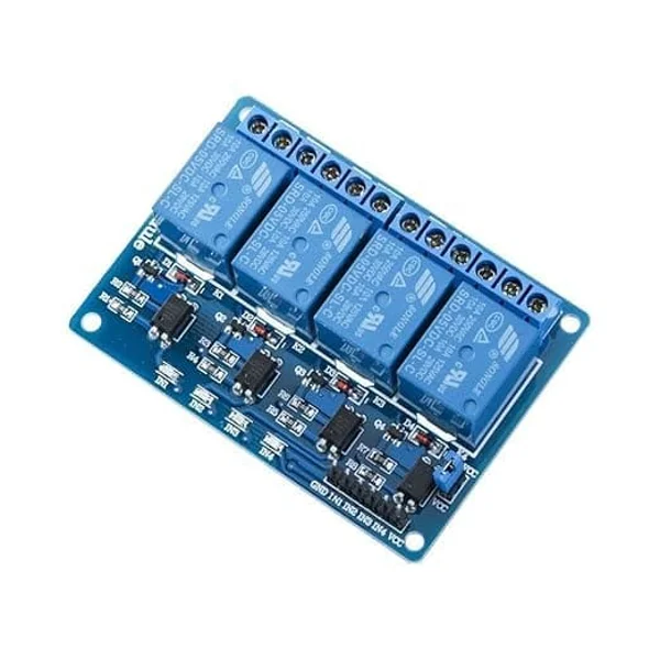
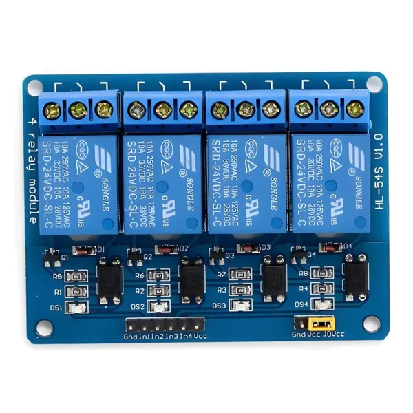

4 Channel 5V Relay Module Board
₹175.00Current price is: ₹175.00. Original price was: ₹295.00.
10 in stock (can be backordered)
Add to cart
Buy Now

You may also like…
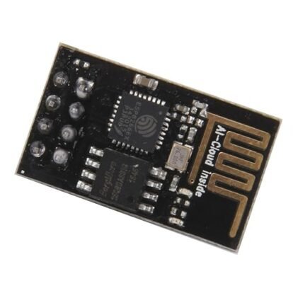
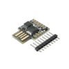
ESP8266 ESP-01 WiFi Transceiver Module Wireless
₹195.00Current price is: ₹195.00. Original price was: ₹289.00.Sale!Hot
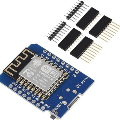
ESP8266 ESP-12F NodeMCU Mini D1 WiFi Development Board
₹270.00Current price is: ₹270.00. Original price was: ₹385.00.Sale!Hot
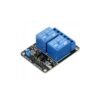
2 Channel 5V Relay Module Board with Optocoupler Isolation
₹189.00Current price is: ₹189.00. Original price was: ₹276.00.Sale!Hot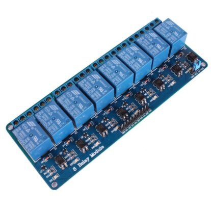
8 Channel Relay 5V Module With Optocoupler
₹327.00Current price is: ₹327.00. Original price was: ₹539.00.Sale!Hot4 Channel 5V Relay Module Board
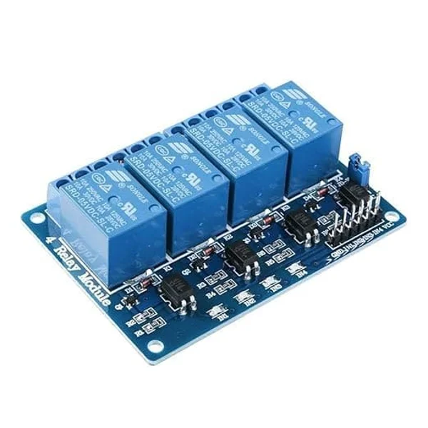
The 4 Channel 5V Relay Module Board is a reliable and efficient electronic switching solution designed for controlling high-voltage AC and DC devices using low-voltage microcontrollers. It is widely used in automation, robotics, and IoT-based control systems.
This versatile 4 Channel 5V Relay Module Board features four independent relay channels with optocoupler isolation, ensuring safe and stable operation by protecting sensitive microcontroller circuits from electrical noise and voltage spikes. It is ideal for smart home systems, industrial automation, agriculture control systems, and IoT projects where multiple devices need to be controlled simultaneously using platforms like Arduino, ESP32, ESP8266, or Raspberry Pi.
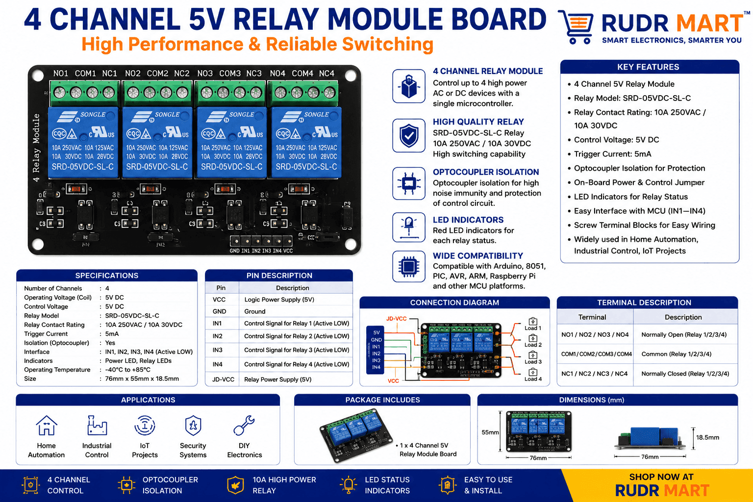
Key Features of the 4 Channel 5V Relay Module Board
Four Independent Relay Channels
The board allows you to control up to four different electrical devices individually or simultaneously. Each channel operates independently, offering maximum flexibility for complex multi-device setups.
Optocoupler Isolation Protection
Safety is paramount in electronics. The 4 Channel 5V Relay Module Board includes onboard optocouplers that provide complete electrical isolation between the low-power control side and the high-power load circuits, safeguarding your microcontrollers from potential back-EMF or voltage surges.
High Load Capacity
Engineered for heavy-duty performance, each channel on this 4 Channel 5V Relay Module Board supports switching loads up to 250V AC at 10A or 30V DC at 10A. This makes it capable of handling standard household appliances, motors, and industrial equipment.
LED Status Indicators
Real-time monitoring is made simple with dedicated LED indicators for each relay channel. When a control signal triggers a relay, its corresponding LED lights up, providing immediate visual confirmation of the switch state.
Easy Microcontroller Interface
Designed with user-friendliness in mind, the input pins (IN1, IN2, IN3, IN4) are fully compatible with standard 5V digital logic systems, allowing direct connection to most development boards without needing complex level-shifter circuits.
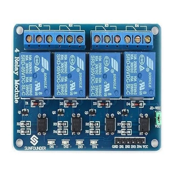
Durable Screw Terminals
The high-voltage side features robust, heavy-duty screw terminals that ensure secure, stable, and long-term wiring installations for all your connected loads.
How the 4 Channel 5V Relay Module Board Works
The 4 Channel 5V Relay Module Board operates by receiving low-voltage digital signals from an external microcontroller. When a digital logic signal (usually LOW or HIGH depending on the jumper configuration) is sent to an input pin, it drives an internal optocoupler.
The optocoupler then triggers the electromagnetic coil inside the relay. This coil creates a magnetic field that physically pulls a flexible armature to switch the contact points from the Normally Closed (NC) position to the Normally Open (NO) position. By isolating the control logic from the load, the 4 Channel 5V Relay Module Board acts as a secure intermediary bridge between delicate microelectronics and heavy mains electricity.
Compatible Development Boards
The universal logic compatibility of the 4 Channel 5V Relay Module Board ensures seamless integration with a vast ecosystem of development platforms:
- Arduino Series: Uno, Nano, Mega, and Pro Mini.
- Espressif Systems: ESP32 Development Boards and ESP8266 NodeMCU.
- Single Board Computers: Raspberry Pi (all generations).
- Other Microcontrollers: STM32 Blue Pill, PIC microcontrollers, and TI MSP430.
Applications of the 4 Channel 5V Relay Module Board
Smart Home Automation
Integrate the 4 Channel 5V Relay Module Board into your home network to control smart lighting, fans, entertainment systems, and automated curtains via smartphone apps or voice commands.
Robotics and Motor Control
Safely switch the power supply of high-current DC motors, linear actuators, and robotic arm mechanisms without risking damage to your central processing unit.
Industrial Automation Systems
Deploy the 4 Channel 5V Relay Module Board in control panels to manage small machinery, conveyor belts, indicators, and pneumatic valves in factory environments.
Agriculture and Irrigation Control
Automate greenhouse setups by using the module to trigger water pumps, misting systems, motorized vents, and artificial growth lights based on sensor data.
Technical Specifications
| Parameter | Specification |
| Product Type | 4 Channel Relay Module |
| Operating Voltage | 5V DC |
| Relay Channels | 4 Channels |
| Max AC Load Capacity | 250V AC @ 10A |
| Max DC Load Capacity | 30V DC @ 10A |
| Circuit Isolation | Optocoupler Based |
| Input Pins | VCC, GND, IN1, IN2, IN3, IN4 |
| Status Indicators | 4 Red/Green LED Status Lights |
| Mounting Mechanism | Fixed PCB Holes for Easy Installation |
Frequently Asked Questions
Is the 4 Channel 5V Relay Module Board compatible with Arduino?
Yes, it is fully compatible with Arduino Uno, Nano, and Mega boards, connecting directly to standard digital I/O pins.
Can it work with 3.3V devices like ESP32 and Raspberry Pi?
Yes, while the board requires a 5V power supply to drive the relay coils, the input trigger pins can often be triggered by 3.3V logic signals from an ESP32 or Raspberry Pi.
What is the purpose of the optocoupler on this board?
The optocoupler provides optical isolation, ensuring that high-voltage spikes from the load side cannot cross over to destroy your microcontroller.
| Weight | 0.65 kg |
|---|---|
| Dimensions | 5.1 × 3.8 × 1.6 cm |
Reviews
There are no reviews yet.