- Empty cart.
- Continue Shopping

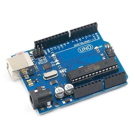
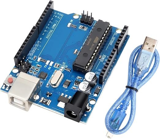
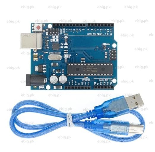
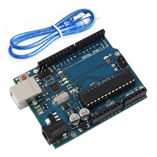
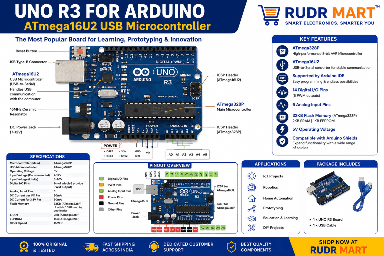
UNO R3 for Arduino ATmega16U2 USB Microcontroller
₹379.00Current price is: ₹379.00. Original price was: ₹579.00.
10 in stock
Add to cart
Buy Now

You may also like…
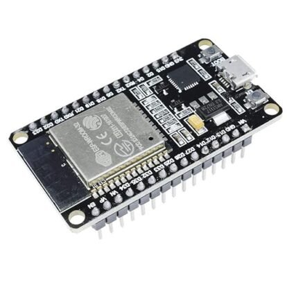
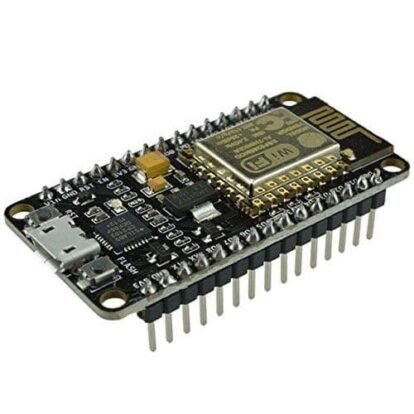
ESP32 IoT Development Board (WiFi + Bluetooth)
₹399.00Current price is: ₹399.00. Original price was: ₹699.00.Sale!Hot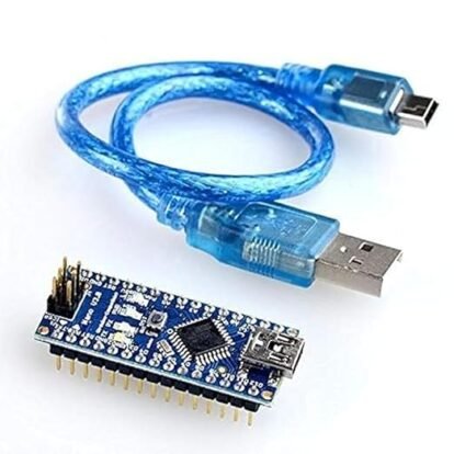
Nano V3.0 Development Board ATmega328P
₹275.00Current price is: ₹275.00. Original price was: ₹579.00.Sale!Hot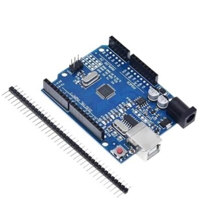
ESP8266 NodeMCU WiFi Development Board (CP2102)
₹370.00Current price is: ₹370.00. Original price was: ₹699.00.Sale!HotATmega16U2 USB Microcontroller
Premium UNO R3 ATmega328P Microcontroller Development Board Compatible Module
The UNO R3 ATmega328P Microcontroller Development Board stands as the definitive standard for engineering students, robotics hobbyists, and professional electronic developers entering the world of embedded systems. Creating automated technology, custom sensor arrays, or internet-of-things (IoT) nodes requires an adaptable processing platform that balances computing power with accessible programming interfaces.
This high-performance hardware architecture provides a reliable, robust, and completely open-source ecosystem that simplifies prototyping. By bridging complex computational logic with real-world physical hardware, it eliminates the entry barriers to hardware engineering, allowing you to seamlessly design, test, and deploy interactive circuits without needing specialized programming gear.
Key Technical Specifications and Core Features
Meticulously engineered to deliver stable performance across a wide range of educational and industrial automation tasks, this board comes packed with industry-standard features:
- High-Performance Core Processing: Powered by the robust ATmega328P 8-bit microcontroller running at a responsive 16 MHz clock speed for handling real-time operations.
- Upgraded USB Communication Layer: Equipped with a high-speed ATmega16U2 USB Microcontroller chip handling USB-to-serial communication, ensuring fast sketch uploads and driverless compatibility.
- Versatile Input/Output Channels: Features 14 digital I/O pins (including 6 hardware PWM channels for precise motor and lighting control) and 6 analog inputs for high-resolution sensor reading.
- Dual-Source Power Management: Features an integrated onboard voltage regulator that safely manages external power inputs between 7V to 12V DC via the barrel jack, or runs directly off 5V USB power.
- Integrated Safety Protections: Outfitted with an resettable onboard polyfuse that automatically shields your computer’s USB ports from accidental short circuits or over-current surges.
ATmega328P Pin Mapping and Layout Architecture
Understanding the physical layout of the UNO R3 platform alongside its integrated ATmega16U2 USB Microcontroller subsystem is key to building error-free circuits. The board is split into two primary rows of female header sockets. The top rail contains the digital pins numbered from 0 to 13, alongside the Ground (GND) and AREF pins. Pins 3, 5, 6, 9, 10, and 11 are explicitly marked with a tilde symbol (~), denoting their hardware pulse-width modulation (PWM) capabilities.
The bottom rail is dedicated to system power distribution and analog data acquisition. Here you will find the dedicated 3.3V and 5V output power pins, two additional GND terminals, a Reset pin, and the Vin terminal for custom power feeds. Right next to the power rail sit the 6 high-resolution analog input pins, labeled A0 through A5, which feature internal successive-approximation analog-to-digital converters (ADC) to precisely translate fluctuating sensor voltages into readable digital data.
Streamlining Embedded Systems Prototyping
One of the most valuable aspects of using an environment featuring the ATmega16U2 USB Microcontroller is its native compatibility with the massive global open-source software library. Because millions of developers rely on this exact serial-to-USB layout, finding pre-tested code libraries for displays, step counters, and data loggers takes just seconds.
The physical header pins are laid out systematically, enabling you to snap on custom expansion shields directly over the top of the main unit. This stackable, modular architecture saves crucial workspace on your test bench and completely cuts out the loose, unreliable wiring webs that typically ruin delicate electrical signals during long-term testing phases involving the ATmega16U2 USB Microcontroller serial pipeline.
Versatile Applications Across DIY Tech and Automation
The sheer utility of this open-source controller makes it an absolute staple across several engineering and robotics fields. When deploying this ATmega16U2 USB Microcontroller driven interface in smart home environments, it serves as an excellent central logic unit, parsing data from temperature, motion, or moisture sensors and driving indicators instantly.
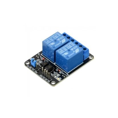
For mechanical and robotics projects, the architecture possesses the precise timing registers needed to coordinate multiple multi-axis movements smoothly. If you are constructing complex automation systems that step up low-power logic to toggle heavy-duty mains appliances safely, you can effortlessly wire your digital I/O pins down to a companion 4 Channel 5V Relay Module Board to build isolated, commercial-grade switching circuits.
Step-by-Step Connection and Getting Started Guide
Getting your initial prototyping script running through the onboard ATmega16U2 USB Microcontroller takes only a few simple preparation steps:
- Connect the board directly to your workstation or laptop using a standard high-quality USB Type-B cable.
- Open your preferred integrated development environment (IDE) and navigate to the board manager layout menu to recognize the active ATmega16U2 USB Microcontroller bridge.
- Select the standard controller configuration along with the active communication COM port assigned by your operating system.
- Write your control logic or load a standard reference script, then hit the upload command to flash the program onto the ATmega328P storage core.

Reviews
There are no reviews yet.